Projection optic system

A technology of projection optical system and optical system, applied in optics, optical components, photography, etc., can solve the problems of environmental control of projection objective lens system (vibration reduction design and temperature control difficulties, etc.), achieve small environmental control design, reduce costs, and reduce volume effect

Active Publication Date: 2009-05-27
SHANGHAI MICRO ELECTRONICS EQUIP (GRP) CO LTD
View PDF5 Cites 0 Cited by
  • Summary
  • Abstract
  • Description
  • Claims
  • Application Information

AI Technical Summary

Problems solved by technology

[0008] In addition, the total optical length in the 352 patent exceeds 1100mm, which will cause great difficulties in the environmental control (vibration reduction design and temperature control, etc.) of the entire projection objective lens system

Method used


Image

  • Projection optic system
  • Projection optic system
  • Projection optic system

Examples


Embodiment Construction

[0018] Below in conjunction with accompanying drawing and specific embodiment, the present invention is explained in more detail:

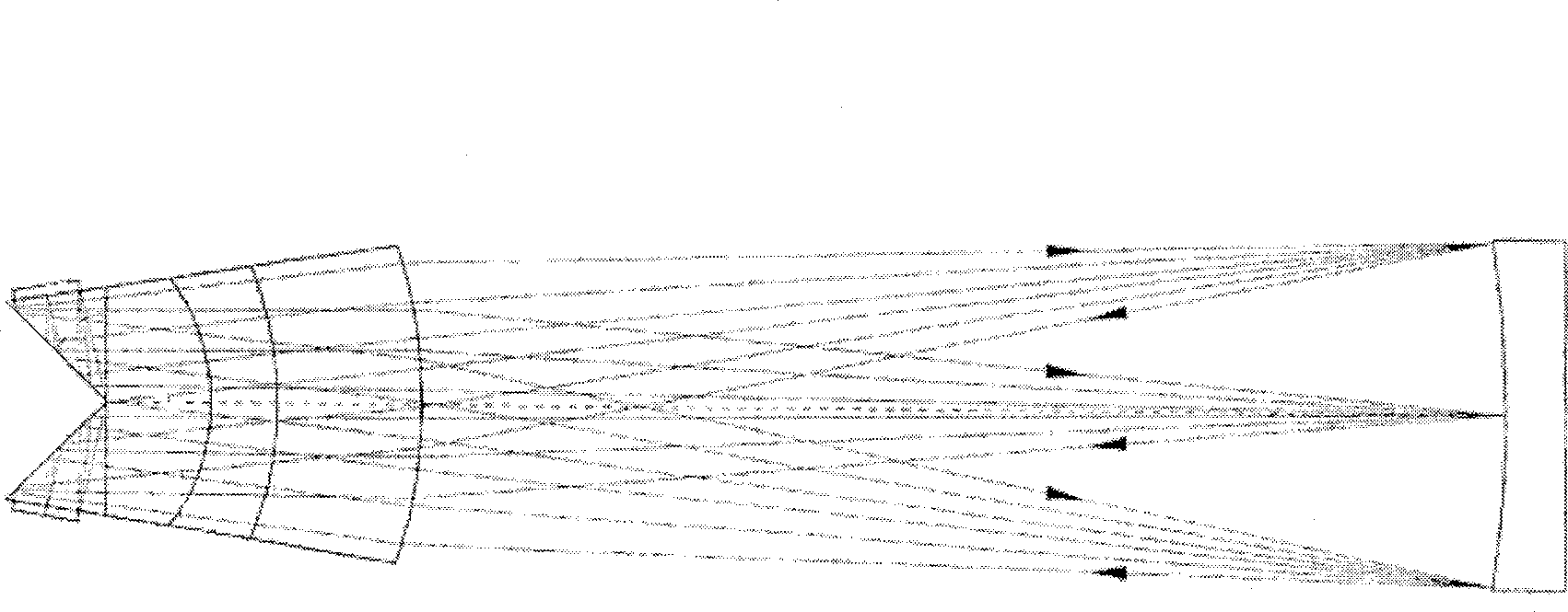
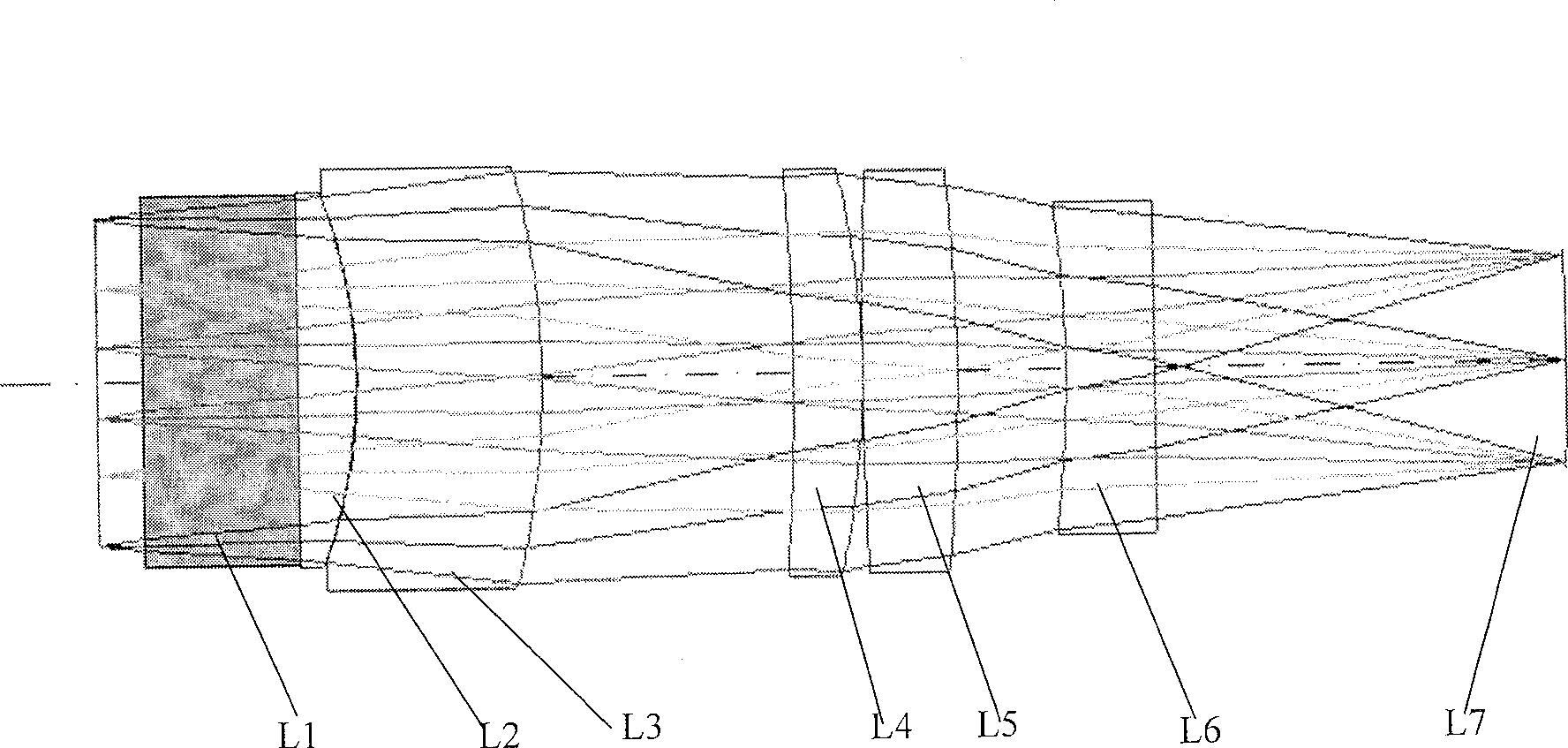
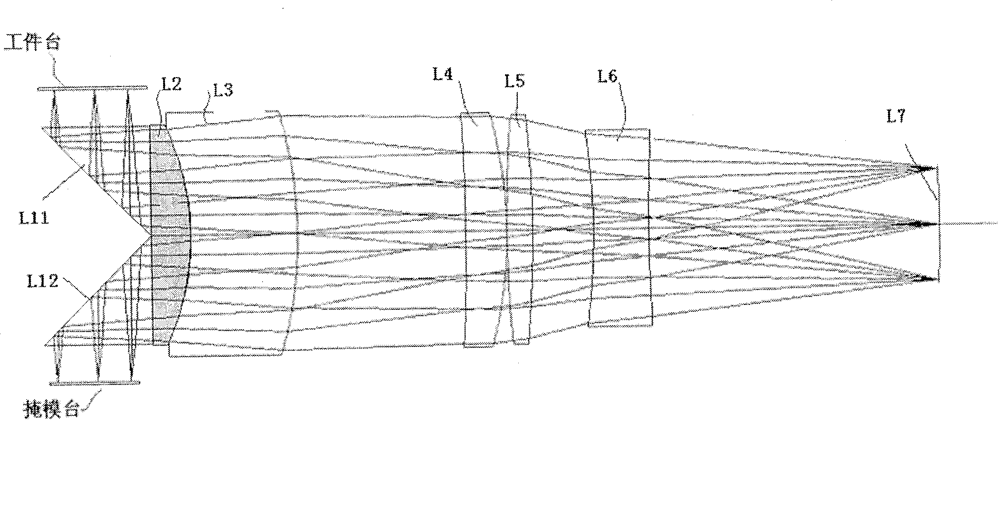
[0019] The present invention relates to a kind of optical system based on Wynne-Dyson structure, is characterized in that on the basis of traditional Wynne-Dyson optical system, inserts another telescopic lens group of positive and negative focal length, is used for reducing the length and the length of the whole optical system Increase the working distance of the optical system.

[0020] The present invention adopts a completely symmetrical optical design with a magnification of -1, and the axial aberration can be completely offset. It is mainly composed of a concave mirror and a mirror group with positive refractive power. The positive field curvature produced by the concave mirror can offset the front positive lens. The negative field curvature generated by the group; the mirror makes the imaging optical path pass through the optical elements o...


PUM

PropertyMeasurementUnit
lengthaaaaaaaaaa

Abstract

Disclosed is a projection optical system. The system comprises a light axle; a concave spherical reflecting mirror; a pair of glass prism, wherein each prism has corresponding first and second plane, the second plane contacts the first converging lens plane along the direction opposite to the light axle, and the first plane orientates to the object plane and the image plane; a converging lens group including a flat convex lens and a meniscus lens, wherein the convex surface orientates to the reflecting mirror; a telescope lens group including a concave-convex lens, a biconvex lens and a biconcave lens; a concave reflecting mirror which concave surface orientates to the object.

Description

Technical field [0001] The invention belongs to photolithography technology in integrated circuit manufacturing process, in particular to a projection optical system. Background technique [0002] With the continuous development of integrated circuits, the minimum line width of transistors continues to shrink. The gate length of transistors in advanced CMOS processes is already less than 0.1 microns. The continuous reduction of feature line width has led to a substantial increase in chip integration, but it has also brought great challenges to the optical lithography process. [0003] In order to obtain a smaller line width, people are also trying to use electron beam lithography, X-ray lithography and ion beam lithography and other alternative methods of optical lithography, but due to the cost, speed and difficulty in mask manufacturing, currently It is also difficult to compete with the optical lithography method, and the optical lithography method is still used in all ...

Claims


Application Information

Patent Timeline
Patent Type & Authority Patents(China)
IPC IPC(8): G03F7/20H01L21/00
CPCG02B17/08G03B27/522G02B13/143G02B13/26G03F7/70225
Inventor 刘国淦蔡燕民
Owner SHANGHAI MICRO ELECTRONICS EQUIP (GRP) CO LTD
Why Eureka
Try Eureka