Electrothermal oil roller system

An oil roller and electric heating technology, which is applied in the direction of rolling, lamination, metal rolling, etc., can solve the problems of low safety factor, broken safety valve, inconvenient operation, etc., increase the service life, prolong the service life, and solve the problem of heat generation serious effect

Active Publication Date: 2009-06-10
上海网讯新材料科技股份有限公司
View PDF2 Cites 0 Cited by
  • Summary
  • Abstract
  • Description
  • Claims
  • Application Information

AI Technical Summary

Problems solved by technology

If the temperature control is not good, the expanding hot oil will often break the safety valve or cause injury accidents. When the cold oil starts to heat, a part of the heater is exposed to the air on the oil surface, which is easy to burn out the heater, the cold oil volume and the oil roller. The setting requirements of the maximum temperature are very strict, the operation is inconvenient, and the safety factor is low
[0004] The commonly used oil roller is filled with heating medium, which has large volume, slow heating, insensitive temperature adjustment, low efficiency and high energy consumption.
[0005] Because the oil roller is a part that works at high temperature, it has strict requirements on the bearings that support it. However, the current ordinary bearing housing does not have the function of cooling the bearing, which causes the bearing to work at high temperature. If it cannot be cooled well, the service life will be shortened. It is greatly reduced, and the high-temperature lubricating grease used often dries up, resulting in poor lubrication and accident shutdown. The service life of the lubricating grease is short and the cost is high under high temperature conditions.

Method used


Image

  • Electrothermal oil roller system
  • Electrothermal oil roller system
  • Electrothermal oil roller system

Examples


Embodiment 1

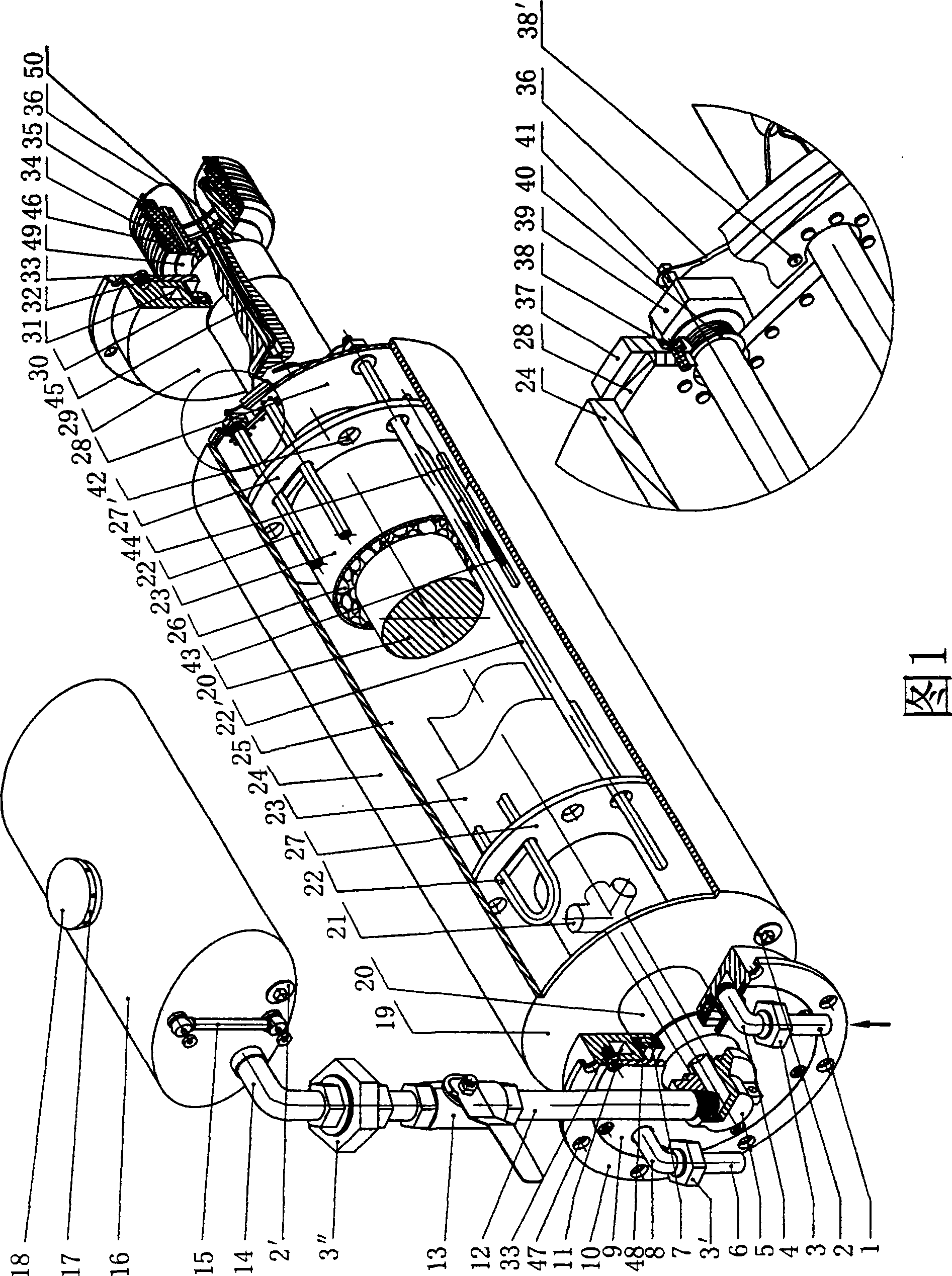
[0035] Please refer to Figure 1. Figure 1 is a schematic structural diagram of an electric heating oil roller system of the present invention. The oil roller assembly, the oil roller supporting and rotating assembly, the oil roller heating assembly, and the oil roller energy storage assembly constitute a complete electric heating oil roller system. The specific structure of each assembly is as follows:

[0036] In the oil roller assembly:

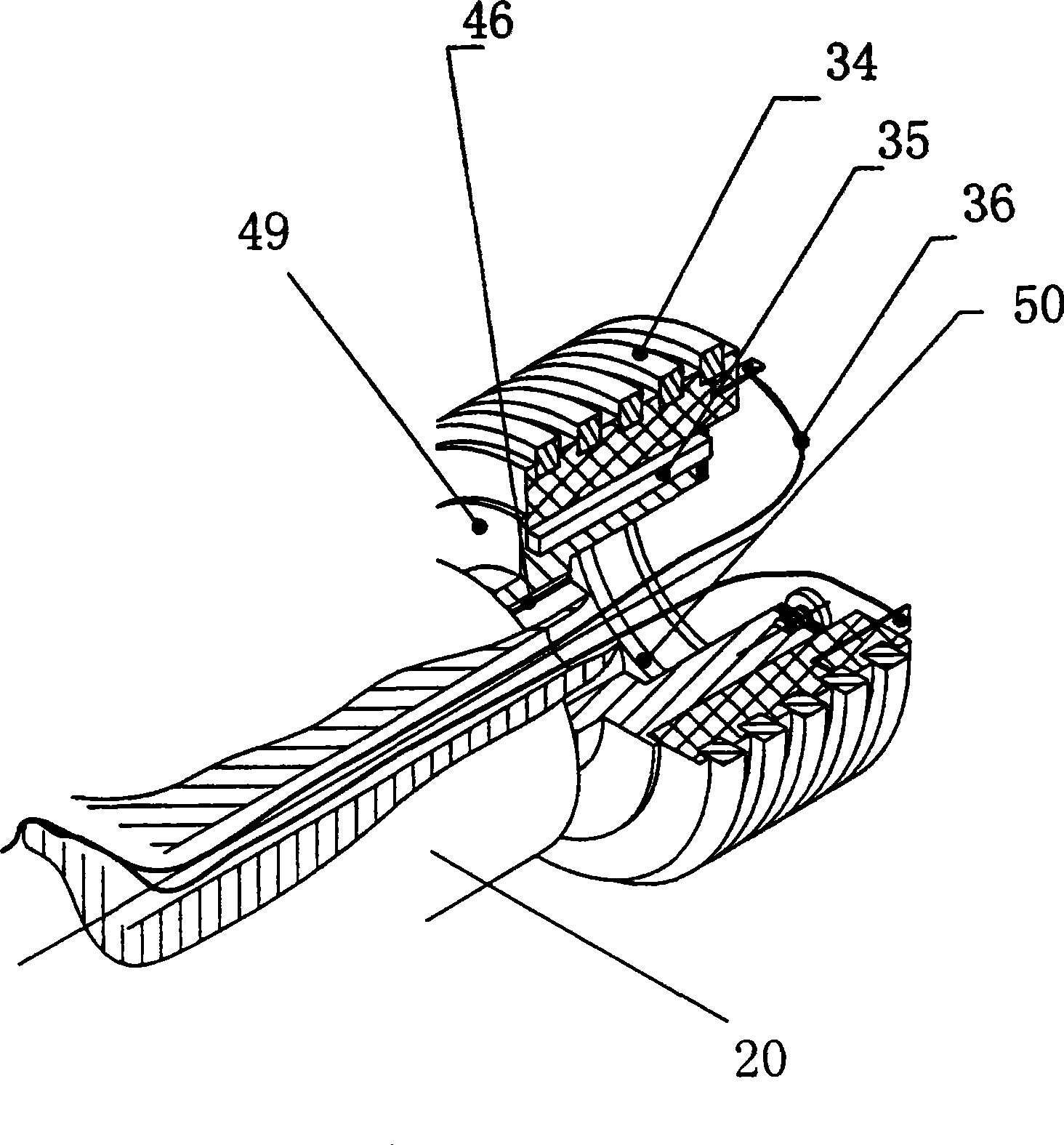
[0037] The hot roller mandrel 20 is in the form of a through shaft or a half shaft. One end is provided with a mandrel oil hole 21 leading from the shaft end and provided with internal threads, a rotary joint is installed as the guide 5, and the other end is provided with a threading hole 45 and a keyway 46 The slip ring 34 is installed, and the shaft end is fixed with a gland 50.

[0038] Two bearing positions are provided on the shoulders on both sides of the heat roller core shaft 20, and the left cooling bearing seat 10 and the right coolin...

Embodiment 2

[0081] The structure of an electric heating oil roller system in Embodiment 2 is basically the same as that in Embodiment 1, except for the structure of the cooling bearing seat.

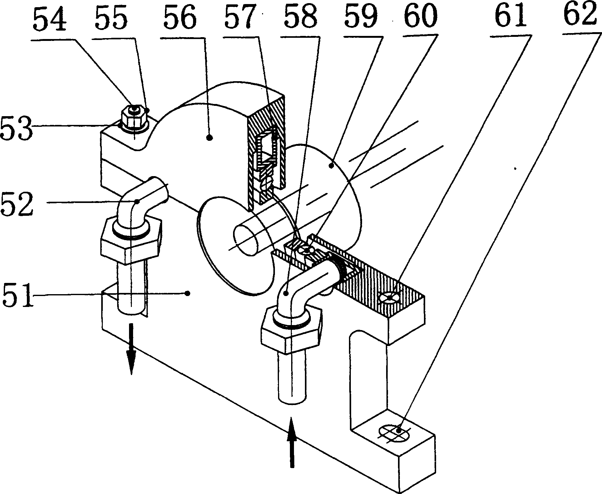
[0082] The cooling bearing seat is an open-close type, and its main structure includes an upper bearing seat, a lower bearing seat, a cooling water jacket, a water inlet pipe and a water outlet pipe.

[0083] The upper bearing seat and the lower bearing seat are correspondingly provided with a semicircular groove. When the upper and lower bearing seats are fixed together, a circular groove is formed, and the cooling water is embedded in the groove The cooling water jacket is made of an annular tube, and the bearing is sleeved in the inner diameter bearing chamber of the cooling water jacket. During installation, first fix the bearing in the bearing position of the hot roller mandrel, then put a cooling water jacket on the outside of the bearing, and then place the cooling water jacket in the semicircula...

Embodiment 3

[0091] The structure of the cooling bearing seat in Embodiment 3 is basically the same as that in Embodiment 2. The difference is that there is a semi-circular ring-shaped cooling water jacket 66 in the upper and lower bearing seats, but the cooling water jacket 66 is independent, and the semi-circular ring tube The two ends are closed and are independently arranged in the lower bearing seat 64 and the upper bearing seat 65.

[0092] The whole of the cooling bearing seat is open and closed, and its main structure includes an upper bearing seat, a lower bearing seat, a cooling water jacket, a water inlet pipe and a water outlet pipe.

[0093] The upper bearing seat and the lower bearing seat are respectively provided with a semicircular bearing chamber corresponding to each other, and a circular bearing chamber is formed when the upper and lower bearing seats are fixed together. When the upper and lower bearing housings are fixed together, the cooling water jacket 66 is still an in...


PUM


Abstract

The electrically heated oil roller system consists of one oil roller assembly, one oil roller supporting and rotating assembly, one oil roller heating assembly and one oil roller energy storing assembly. The oil roller supporting and rotating assembly has bearings on cooling bearing seats. The oil roller heating assembly is set inside the cavity between the inside heating jacket and the outer heating jacket inside the oil roller assembly. There are one guide unit of hot oil conveying pipeline communicated to the oil roller energy storing assembly in the left end of the oil roller assembly, and one collector ring in the right end of the oil roller assembly. The electrically heated oil roller system of the present invention has high heat energy utilizing rate, capacity of increasing the service life of bearing, simple structure, high use efficiency and less maintenance.

Description

Technical field [0001] The present invention relates to a heating device, in particular to an electric heating oil roller system for composite foil and plate rolling. The system uses an internal electric heater to heat a heat transfer medium and conducts the heat to the surface of the oil roller to heat it The composite substrate passing through the guide roller. Background technique [0002] At present, there are mainly two types of electric heating rollers on the market, one is an ordinary roller without heat transfer medium, and the other is an oil heating roller containing heat transfer oil. Ordinary rollers use heaters in the rollers for radiant heating, and the heat is transferred to the metal shell of the outer diameter of the heat roller through air. Such electric heating rollers will have problems such as uneven surface temperature, large temperature difference, and high energy consumption during the application process, and the heat source cannot be fully utilized. Howe...

Claims


Application Information

Patent Timeline
Patent Type & Authority Patents(China)
IPC IPC(8): B32B37/06B21B47/00B21B37/74B21B27/06
Inventor 付瑞英孙继光苏彭恩黄真辉
Owner 上海网讯新材料科技股份有限公司
Why Eureka
Try Eureka