
Straightening machine frame pretightening technology

A technology of straightening machine and frame, which is applied in the field of straightening process of tube and bar straightening machine, which can solve the problems of insurmountable straightening accuracy and achieve the effect of ensuring accuracy

Active Publication Date: 2009-06-24
JINAN HEAVY MACHINERY JOINT STOCK
View PDF3 Cites 0 Cited by
  • Summary
  • Abstract
  • Description
  • Claims
  • Application Information

AI Technical Summary

Problems solved by technology

[0005] The purpose of the present invention is to solve the problem that the current straightening machine cannot overcome the problem that the straightening accuracy is affected by the uneven residual pre-tightening force of the column. Straightening machine frame pre-tightening process

Method used


Image

  • Straightening machine frame pretightening technology
  • Straightening machine frame pretightening technology
  • Straightening machine frame pretightening technology

Examples


Embodiment Construction

[0032] The present invention will be further described below in conjunction with the accompanying drawings and embodiments.

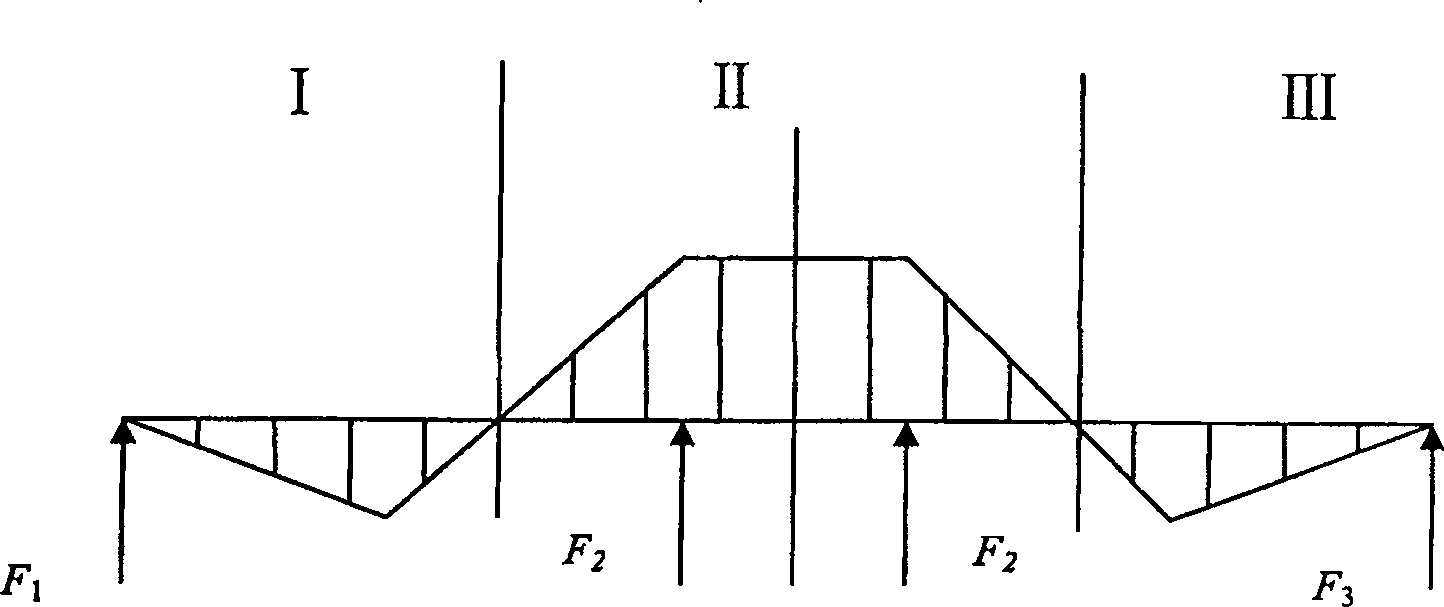
[0033] figure 1 , is the distribution map of the stress area of ​​the roll. F in the picture 1 ——Front Roller Force——Zone I, F 2 ——The force of the middle roller——Zone II, F 3 ——Rear roller force——Zone III.

[0034] It can be seen from the figure that compared with the front and rear area rollers, the flattening force of the middle roller on the pipe is much greater, and the corresponding straightening force transmitted to the upper and lower beams is not uniform. Therefore, the present invention adjusts the pre-tightening force by distributing the pre-tightening force in proportion to improve the whole load system.

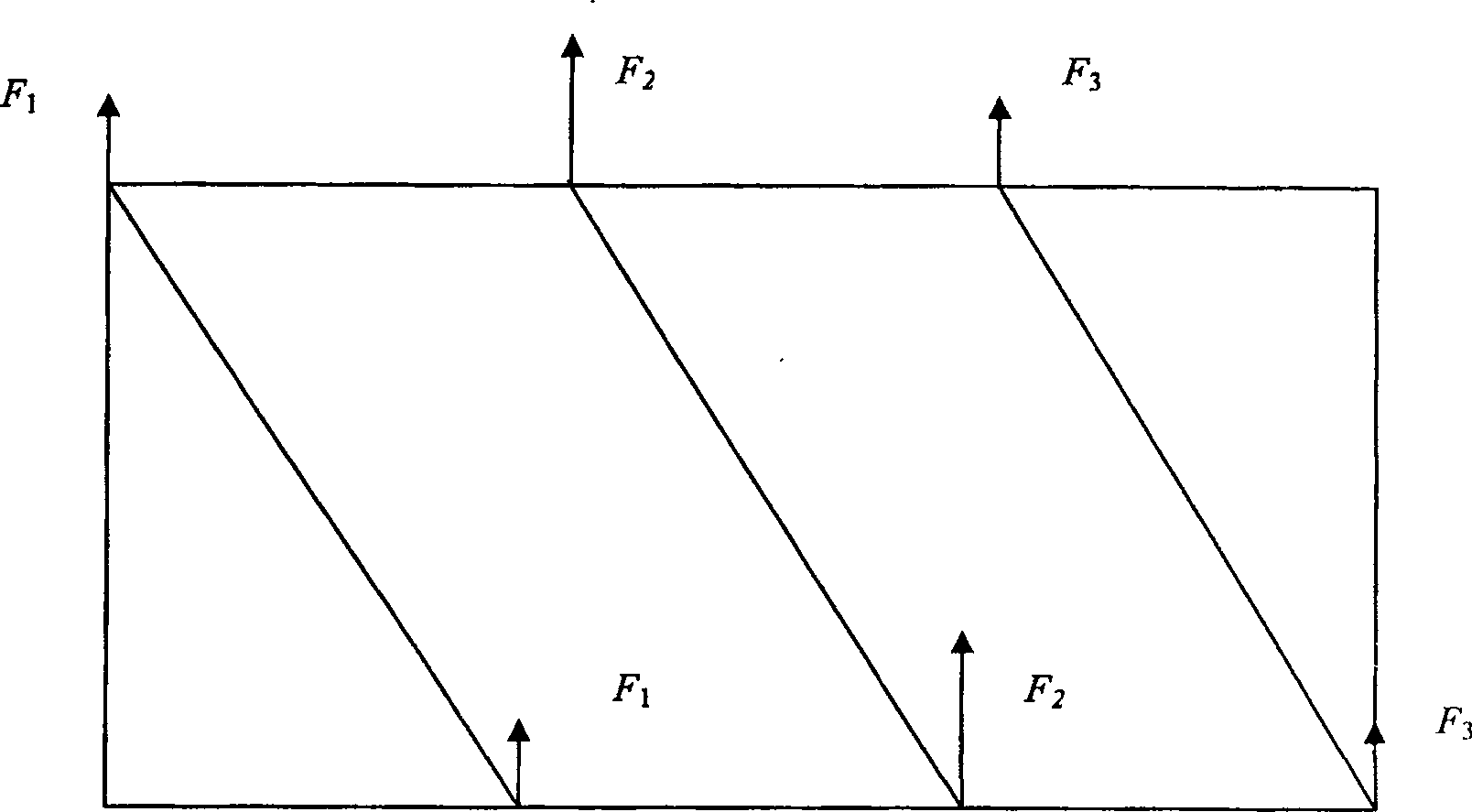
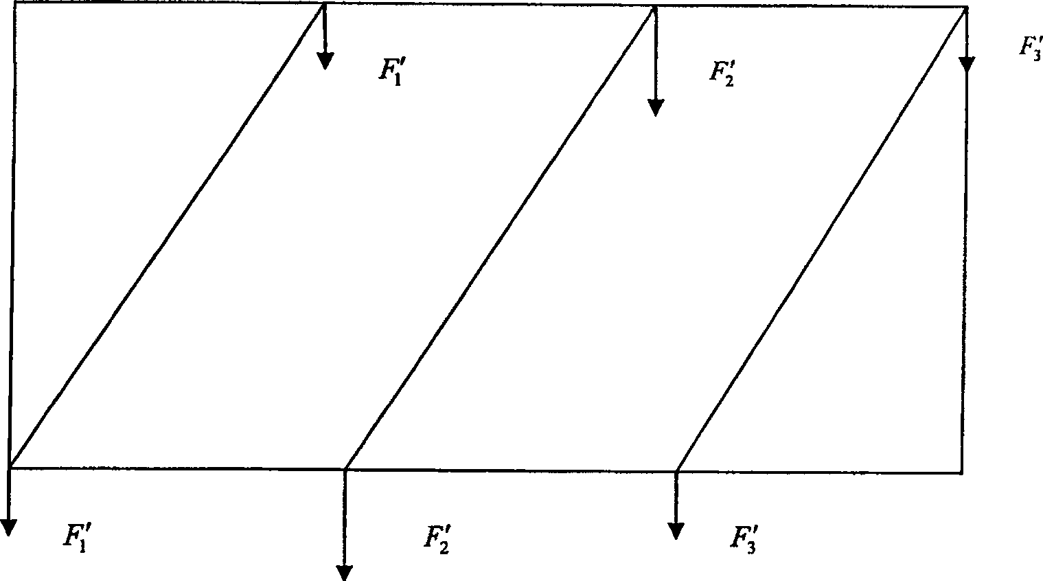
[0035] figure 2 , image 3 , Figure 4 middle, figure 2 is the force diagram of the upper beam in the working state, image 3 is the force diagram of the lower beam under working condition, Figure 4 It is the resultant force ...


PUM


Abstract

The invention discloses a frame pre-tightening process of a straightening machine. It can effectively solve the influence of residual preload and improve straightening accuracy. The specific method is: 1) Divide the stress-bearing area of ​​the rolls of the straightening machine into three areas: the front roll area, the middle roll area and the rear roll area; 2) According to the straightening force of each roll, it can be obtained The working loads F1, F2, F3...Fn of the beam and the working loads F1', F2', F3'...F'n transmitted to the lower beam; 3) Determine the weight of the upper beam G / N, where G is the gravity of the upper beam, and N is the number of columns; 4) According to the resultant force of the column in the working state and the gravity of the upper beam, determine the tensile load borne by each column: Fn=Fn+F'n+G / N; 5) According to the above formulas, the pre-tightening force should be applied to each column: F'=mF, m is the pre-tightening coefficient. 6) One value can be taken for the m of N columns; it is also possible to take different values ​​for the m of N columns to obtain the resultant force ratio of different columns, and then distribute the preload coefficients of different columns according to the reciprocal of the resultant force ratio: mn=( F combined with n+1 / F combined with n)(mn-1)+1.

Description

technical field [0001] The invention relates to a straightening process of a tube and rod straightening machine, in particular to a pre-tightening process of a straightening machine frame. Background technique [0002] At present, the oblique roller straightening method is specially used for straightening the round section bar. The roller and the round bar are obliquely intersected. When the roller rotates, it rotates and advances. The orientation of is changed in a spiral pattern. This is an all-round straightening method. Since the original bending of the round material may exist in any direction, that is, there is a three-dimensional bending, it is especially suitable for the skewed roller straightening method. [0003] Most of the tube and bar straightening machines are multi-column upper and lower beam structures, and the frame is fixed by bolt pre-tightening. The rigidity of the rack is ensured by applying bolt pre-tightening force to each column. The traditional pr...

Claims


Application Information

Patent Timeline
Patent Type & Authority Patents(China)
IPC IPC(8): B21D3/02
Inventor 阎洪涛许京伟
Owner JINAN HEAVY MACHINERY JOINT STOCK
Learn More