
Distributing element

An appliance and wiring technology, applied in the direction of electrical components, circuits, connections, etc., can solve problems such as poor contact, and achieve the effect of increasing the degree of freedom of design and reducing the number of parts

Inactive Publication Date: 2009-06-24
MATSUSHITA ELECTRIC WORKS LTD
View PDF2 Cites 0 Cited by
  • Summary
  • Abstract
  • Description
  • Claims
  • Application Information

AI Technical Summary

Problems solved by technology

In this terminal structure, just insert the wire into the wire insertion hole provided on the back of the appliance body to prevent the connection of the wire from falling off, but when the insertion amount of the wire into the wire insertion hole is not enough, defects such as poor contact may occur

Method used


Image

  • Distributing element
  • Distributing element
  • Distributing element

Examples


Embodiment 1

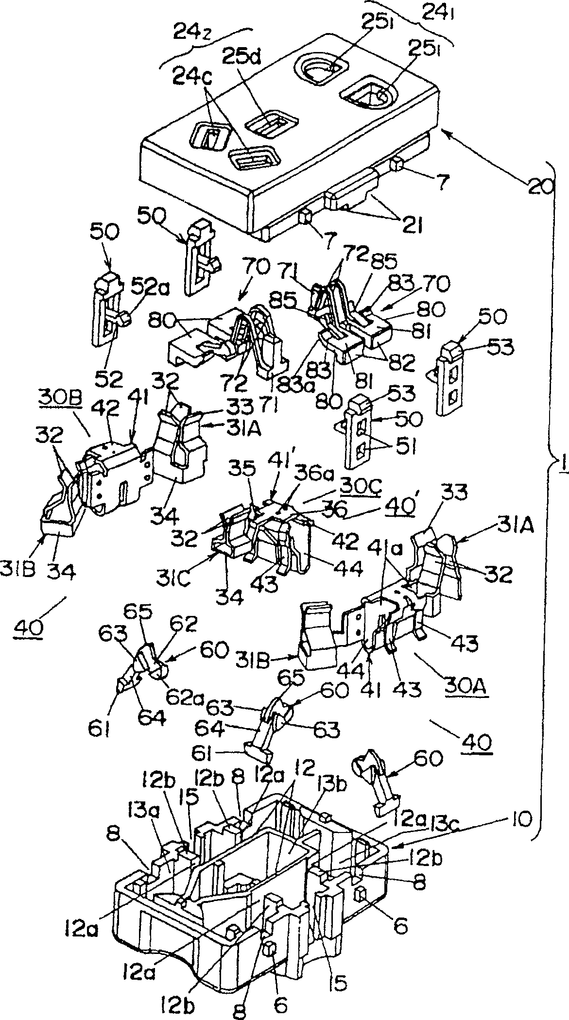
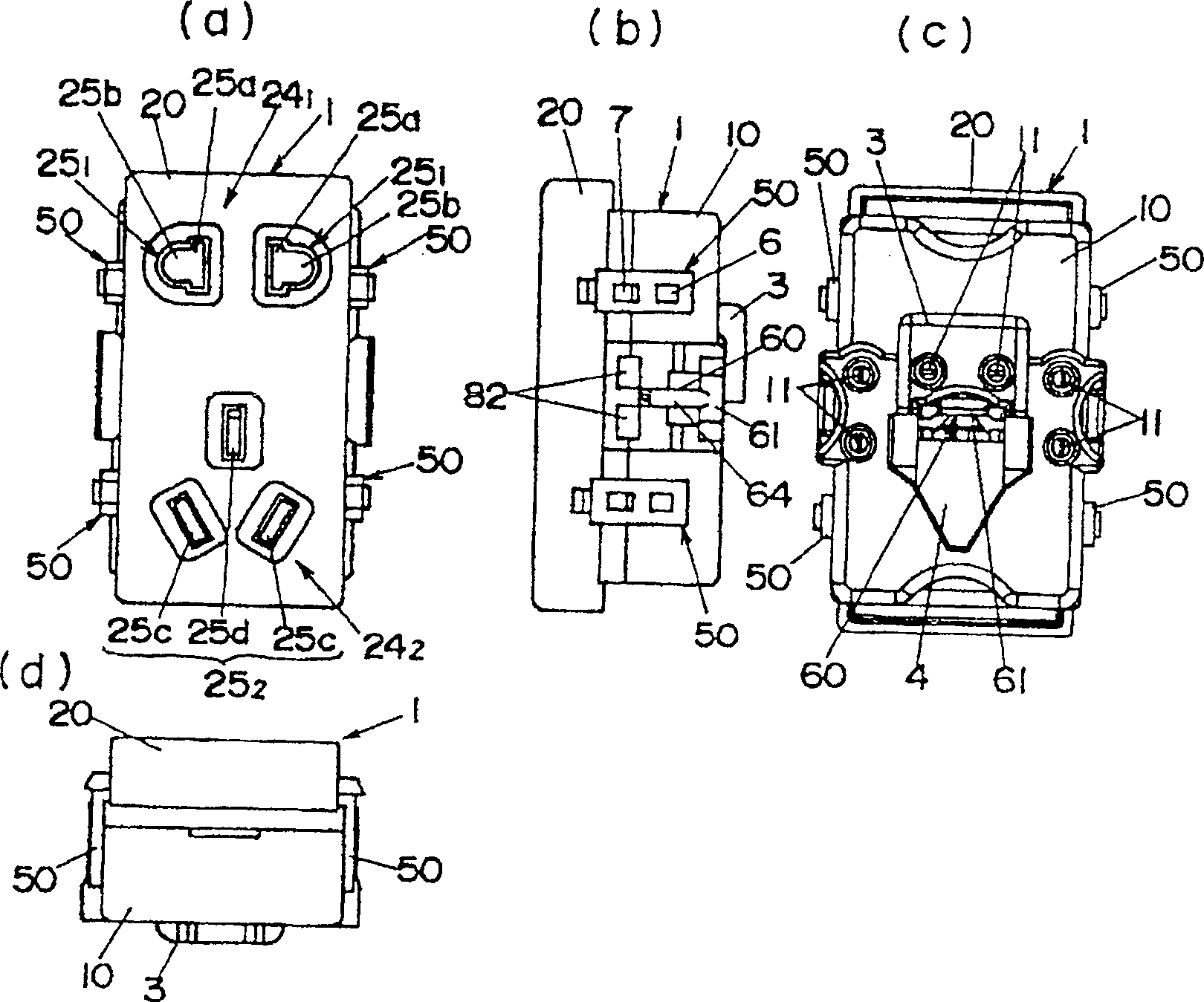
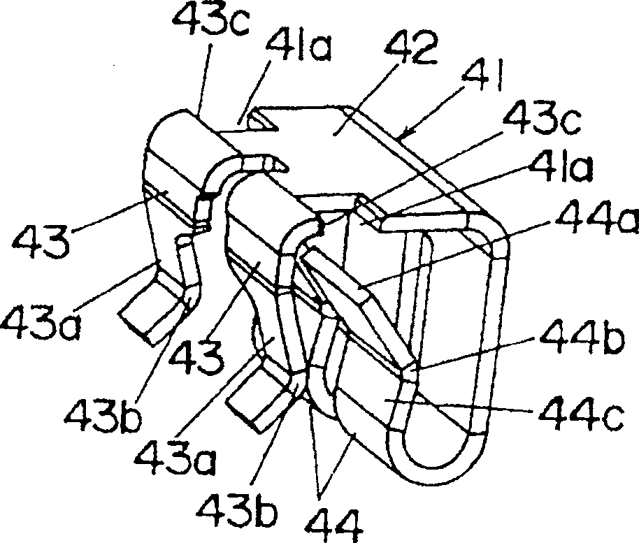
[0032] The socket of this embodiment is as figure 1 and figure 2 As shown, there is an appliance body 1, which is composed of the following components. The body 10 is formed into a rectangular parallelepiped with an open front using a thermosetting synthetic resin with excellent tracking resistance; and the cover 20 is also made of an anti-leakage Thermosetting synthetic resin excellent in tracking property is formed into a rectangular parallelepiped with an open back.

[0033] The body 10 divides the inner space into three parts by a plurality of partition walls 12 disposed along the longitudinal direction. Again, partition walls (not shown) are also formed in the lid 20. After the body 10 and the lid 20 are combined, the internal space of the appliance body 1 is divided into three independent chambers (storage chambers) by the partition wall 12 between the body 10 and the lid. 13a, 13b, 13c). Moreover, the storage chambers 13a and 13b at both ends are subdivided into thr...

Embodiment 2

[0058] In the first embodiment, the connection with the terminal portion 40 is released, and the display member 80 is returned from the protruding position to the non-protruding position by pressing the display portion 82 by hand after pulling out 101 from the wire insertion hole 11 . However, the present embodiment is characterized in that the display member 80 is returned from the protruded position to the non-protruded position by the release button 60 that releases the connection between the electric wire 101 and the terminal portion 40, and other structures are the same as in the first embodiment. Therefore, the same reference numerals are assigned to the same components as in the first embodiment, and descriptions and illustrations are omitted.

[0059] In this embodiment, the release button 60 is as Figure 10 As shown, an approximately triangular driving piece 66 protruding parallel to the end surface of the connecting portion 64 and the support portion 65 is provided,...


PUM


Abstract

The present invention seeks to be able to confirm in a simple manner whether electric wires and terminal parts are connected. In order to achieve the aforementioned object, the present invention provides a wiring appliance, in which a terminal portion (40) for connecting electric wires inserted through the electric wire insertion holes in a quick connection manner is provided. Also equipped with a display member (80), the display part (82) is stored in the wiring appliance so as to be free between a non-connecting position protruding outside the appliance body (1) and a connecting position not protruding outside the appliance body (1). The movement is driven by the electric wire connected to the terminal part (40), and moves from the non-connection position protruding outward of the appliance body (1) to the connection position not protruding outward of the appliance body (1). That is, if the wire is inserted into the wire insertion hole (11) and connected to the terminal portion, the display portion (82) protrudes outside the appliance body (1) due to the display member (80) moving from the non-protruding position to the protruding position, so there is no need to By observing the confirmation window, it is also possible to simply confirm whether the electric wire and the terminal part are connected according to whether the display member protrudes out of the appliance body (1).

Description

technical field [0001] The present invention relates to a wiring appliance such as a switch or a socket, in particular to a wiring appliance with a quick-connect terminal portion. Background technique [0002] Conventionally, in wiring devices such as switches and receptacles, the main purpose is to simplify the wiring work, and a quick-connect terminal structure (so-called screwless terminal) is used for the terminal portion for connecting electric wires. In this terminal structure, only the wires are inserted into the wire insertion holes provided on the back of the appliance body to prevent the connection of the wires from falling off, but when the insertion amount of the wires to the wire insertion holes is insufficient, defects such as poor contact may occur. [0003] However, not only wiring devices such as switches and sockets, but also other electrical appliances such as circuit breakers employ the above-mentioned quick-connect terminal structure (see Patent Document...

Claims


Application Information

Patent Timeline
Patent Type & Authority Patents(China)
IPC IPC(8): H02G3/02H01R4/48H01R4/26
Inventor 本田稔
Owner MATSUSHITA ELECTRIC WORKS LTD
Learn More