Connection system, control method, image processing apparatus, and communication method
A technology of image processing device and connection system, which is applied in the direction of image communication, electrical components, etc., and can solve problems such as devices that cannot be easily confirmed for connection
- Summary
- Abstract
- Description
- Claims
- Application Information
AI Technical Summary
Problems solved by technology
Method used
Image
Examples
no. 1 approach
[0065] [1.1 Overall composition]
[0066] [1.1.1 System composition]
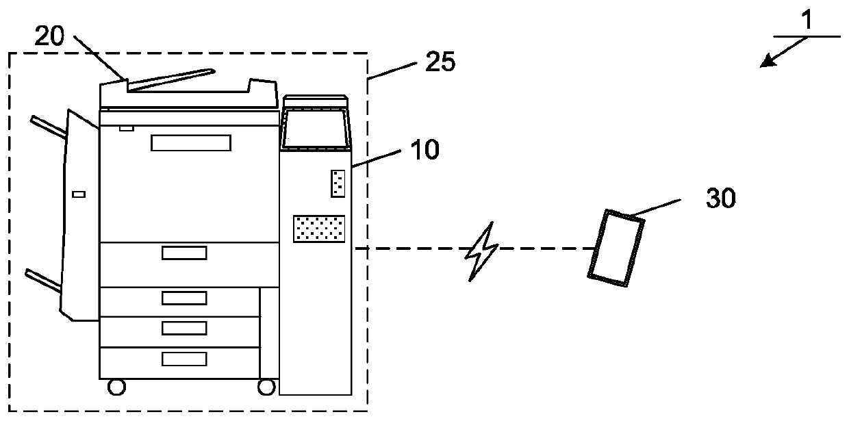
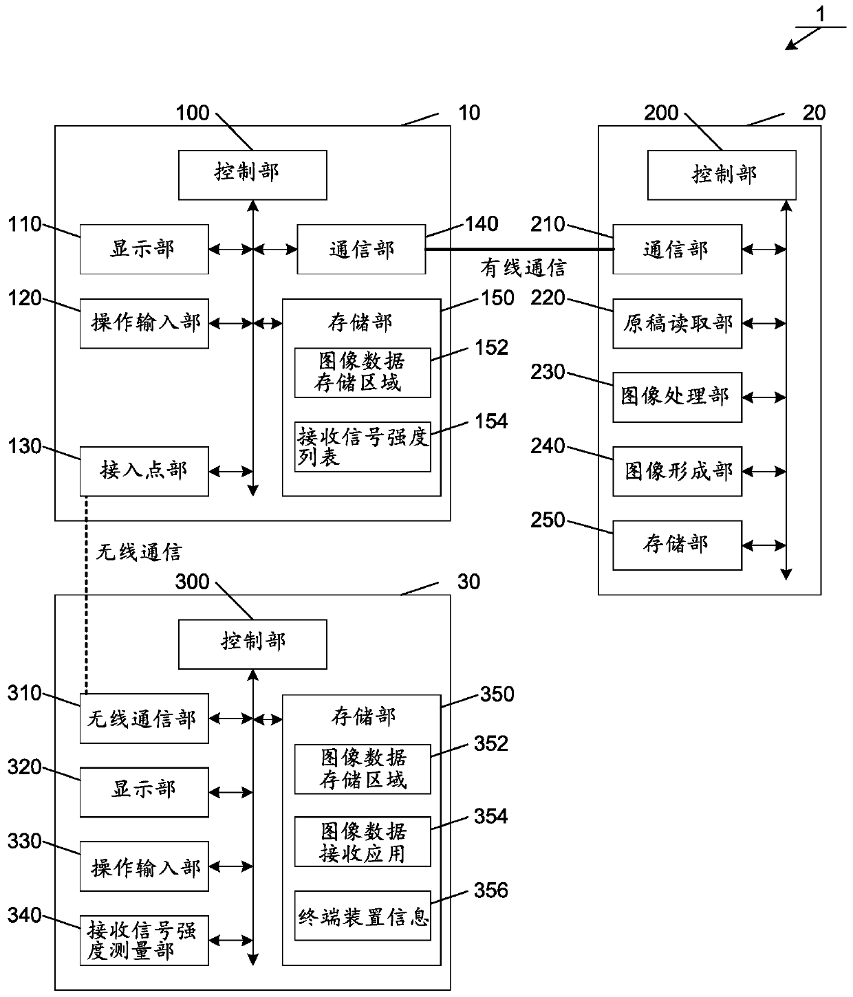
[0067] based on figure 1 The overall configuration of the system 1 of this embodiment will be described. Such as figure 1 As shown, the system 1 is composed of a processing device 10 , an image forming device 20 and a terminal device 30 . also, figure 1 A case in which one terminal device 30 is connected to the processing device 10 is shown, but a plurality of terminal devices 30 may be connected to the processing device 10 . In addition, the processing device 10 and the image forming device 20 may be configured as a device including the processing device 10 and the image forming device 20 (for example, the image processing device 25 ).
[0068] The processing device 10 is a device connected to the image forming device 20 . The image forming device 20 is a device that outputs an image by forming an image of image data input from the outside on recording paper or the like, and is a device called a mult...
no. 2 approach
[0205] Next, a second embodiment will be described. The second embodiment is an embodiment in which image data transmission is interrupted when a plurality of terminal devices 30 having the same information as the terminal device 30 are connected during the terminal name display process. This embodiment combines the first embodiment Figure 6 replace with Figure 12 . In addition, the same code|symbol is attached|subjected to the same functional part and process, and description is abbreviate|omitted.
[0206] refer to Figure 12 The terminal name display processing of this embodiment will be described. In the description of the processing, the case where the terminal name is used as the information of the terminal device 30 has been described, but the user's account name and a terminal identifier other than the terminal name may be used as the information of the terminal device 30 .
[0207] In step S186, when the received signal strength list 154 stores the information ...
no. 3 approach
[0214] Next, a third embodiment will be described. The third embodiment is an embodiment in which session-specific information is displayed together with information on the terminal device 30 in the terminal name display process. For example, a part of the session ID (specifically, the first four characters of the session ID) is displayed as an identification number. In this way, the user can identify the terminal device 30 with which the session is established using the terminal name and identification number.
[0215] Figure 14 It is a figure which shows the operation example of this embodiment. In step S188 and step S192 of the terminal name display process, as Figure 14 As shown in the display screen W300 of (a), the control unit 100 displays the terminal name and session specific information on the display unit 110 . Also, in S110 or S120, such as Figure 14 As shown in the display screen W302 of (b), the control unit 300 displays the session-specific information t...
PUM
 Abstract
Description
Claims
Application Information
 - R&D
- Intellectual Property
- Life Sciences
- Materials
- Tech Scout
- Unparalleled Data Quality
- Higher Quality Content
- 60% Fewer Hallucinations
Browse by: Latest US Patents, China's latest patents, Technical Efficacy Thesaurus, Application Domain, Technology Topic, Popular Technical Reports.
© 2025 PatSnap. All rights reserved.Legal|Privacy policy|Modern Slavery Act Transparency Statement|Sitemap|About US| Contact US: help@patsnap.com


