Face light source module based on LED

A technology of light emitting diodes and surface light sources, applied in optics, light guides, optical components, etc., can solve the problems of difficult to break through the upper limit of the principle light guide efficiency, cannot reach higher, the upper limit of light guide efficiency, etc., and achieve a good home decoration effect. Effect

Inactive Publication Date: 2009-07-01
TSINGHUA UNIV
View PDF9 Cites 12 Cited by
  • Summary
  • Abstract
  • Description
  • Claims
  • Application Information

AI Technical Summary

Problems solved by technology

Although the light guide efficiency can be maximized by optimizing the design of the scattering mechanism layer and the scattering unit, since the light will inevitably transmit from the main surface opposite to the main exit surface and become invalid exit light, there is a principle of its light guide efficiency. upper limit and cannot reach higher
The surface light source devices based on light-emitting diodes that have appeared now, such as the surface light source structure disclosed in Chinese Invention Patent Application 03101472.0 and Chinese Utility Model Patent 01267387.0, have similar principles to the above, so it is difficult to break through the above-mentioned upper limit of theoretical light guide efficiency

Method used


Image

  • Face light source module based on LED
  • Face light source module based on LED
  • Face light source module based on LED

Examples


Embodiment 1

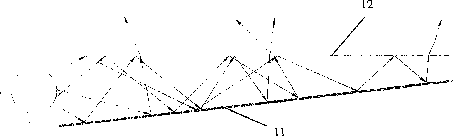
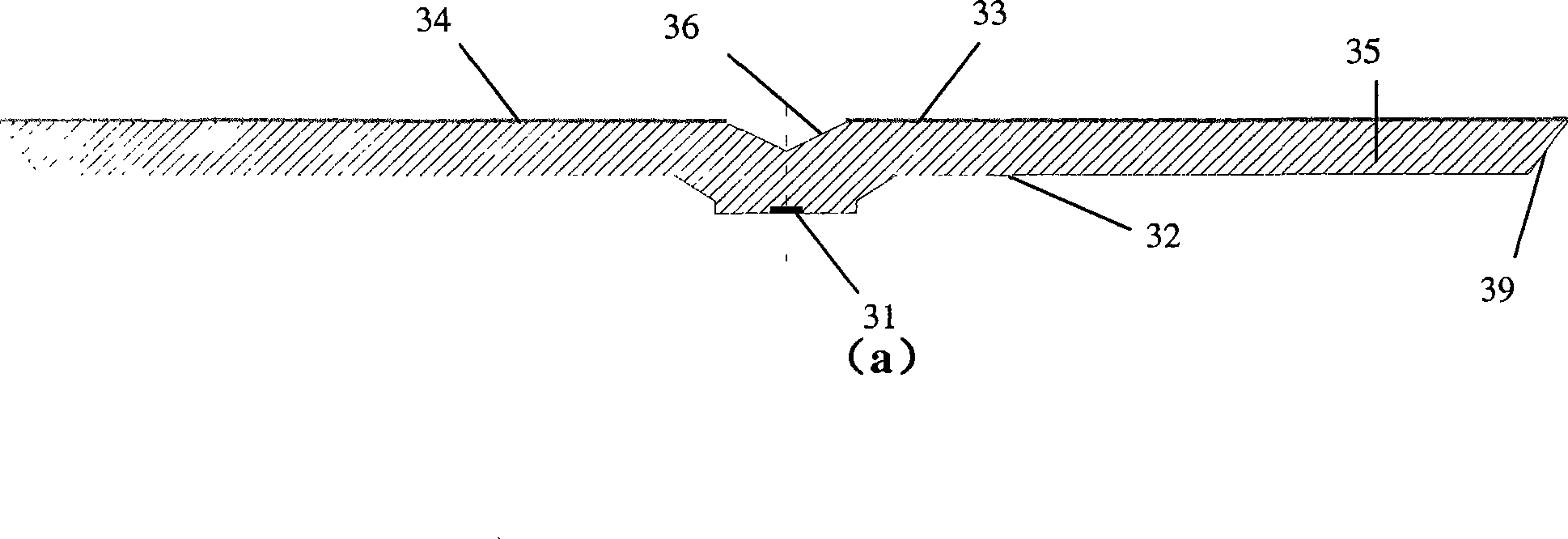
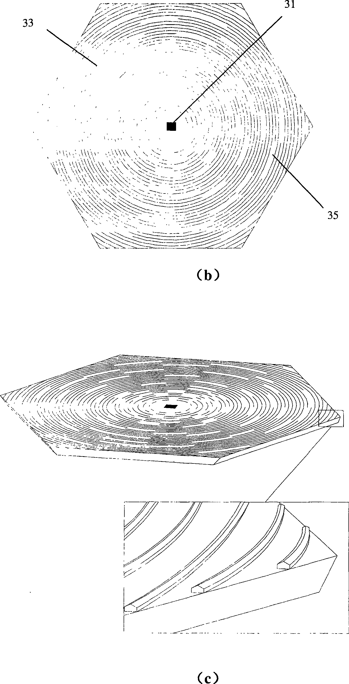
[0051] Example 1 is as Figure 4 The surface light source module based on light emitting diodes 31 is shown. In embodiment 1, a primary light source is used, the core part of which is a single LED chip, and the light source is placed at the geometric center of the surface light source module. The projection of the light emission guide structure 33 in the first embodiment on the main emission surface 34 is a circular arc centered on the projection point of the primary light source on the main emission surface 34 .

[0052] The critical condition for total reflection of light at the PMMA-air interface is:

[0053]

[0054] When the incident angle of light θ i Satisfy

[0055] θ i ≥θ ic

[0056] When , the light is now totally reflected at the PMMA-air interface, and this condition is called the total reflection condition hereinafter.

[0057] Such as Figure 4 As shown, the light emitted by the primary light source is divided into four parts according to the included ...

Embodiment 2

[0062] The surface light source module based on light-emitting diodes in Embodiment 2 is different from Embodiment 1 in that the longitudinal section shape of the light emitting guide structure 33 is different. Here, the different parts will be mainly explained, and the repeated description of the same parts will be omitted.

[0063] The longitudinal section shape and local light paths of the light exit guide structure 33 of Embodiment 2 are as follows: Figure 5 shown. It can be seen that the light partially incident on the light exit guiding structure 61 does not satisfy the total reflection condition at the interface and exits from the main exit surface 34 . Similarly, because there is almost no useless outgoing light emitted from the lower surface 32 of the light guide plate, the total light guide efficiency of the light guide plate 35 can reach a level similar to that of Embodiment 1, but the distribution of light emission angles is slightly different from Embodiment 1. ...

Embodiment 3

[0064] The surface light source module based on the light emitting diodes 31 of the third embodiment is different from the first embodiment in that the specific projection shape of the light emitting guide structure 33 on the main emitting surface is different. The different parts are explained here emphatically, and repeated explanations for the same parts are omitted.

[0065] The top view of the surface light source module of Embodiment 3 is as follows Image 6shown. The projection of the light emitting guiding structure 71 on the emitting main surface 34 is a straight line segment, but still satisfies the condition of a circular arc with the projection point of the primary point light source on the emitting main surface 34 as the center of the circle, that is, from the primary point light source 31 to the The included angle (acute angle) between the connection line 72 of any point A on the light emission guide structure 33 and the tangent line 73 of the straight line or c...


PUM

PropertyMeasurementUnit
refractive indexaaaaaaaaaa

Abstract

The surface light source module based on light-emitting diodes belongs to the field of light-emitting diode packaging and application technology, and is characterized in that it includes light-emitting diodes and a light guide plate that diffuses the light emitted from the light-emitting diodes to a main exit surface, on which the main exit surface There are several light emitting guiding structures that protrude from the main emitting surface and extend in an approximate arc shape, and the arc is any kind of straight line or curve, which is based on the projection of the light emitting diode light source on the main emitting surface. The point is approximately central. The principal surface facing the liquid crystal layer in a liquid crystal display, or the plane used for illumination in an illuminating device are the main outgoing surfaces. The secondary packaging efficiency of the present invention reaches 80%, which is more than 30% higher than the highest level of current products; the ratio of the light intensity of the brightest point of the surface light source to the light intensity of the weakest point is 1.2, realizing uniform light output. It is used to manufacture a surface light source device with uniform light output, large light output area and high color rendering index.

Description

field of invention [0001] The invention relates to a surface light source module based on light emitting diodes, belonging to the technical field of light emitting diode packaging and application. The present invention is applicable to backlight sources of liquid crystal display devices mounted on equipment such as personal computers, vehicle navigation systems, and hand-held phones, and is also applicable to ordinary indoor lighting lamps. Background technique [0002] So far, the backlight used by liquid crystal display devices mainly uses rod-shaped fluorescent lamps (cold cathode tubes) as the primary light source, and its optical path diagram is as follows figure 1 As shown, the scattering mechanism layer 11 is distributed on the main surface opposite to the main output surface, and its function is to change the original optical path so that the light is emitted from the main output surface 12 through reflection. And because the color rendering index (CRI) of the cold ...

Claims


Application Information

Patent Timeline
Patent Type & Authority Patents(China)
IPC IPC(8): H01L33/00H01L25/075G02B6/00G02F1/13357
Inventor 罗毅钱可元杨毅韩彦军
Owner TSINGHUA UNIV
Why Eureka
Try Eureka