
Device for transporting fuel from a reservoir to an internal combustion engine

一种内燃机、容器的技术,应用在与内燃机燃料供给结合的布置、液体燃料给料机、动力装置等方向,能够解决装配成本和制造成本高等问题,达到简单方式、降低制造成本的效果

Active Publication Date: 2009-07-15
ROBERT BOSCH GMBH
View PDF7 Cites 0 Cited by
  • Summary
  • Abstract
  • Description
  • Claims
  • Application Information

AI Technical Summary

Problems solved by technology

The disadvantage is that the drive line has to be assembled in the device as a single piece
As a result, the assembly and manufacturing costs of the device are relatively high

Method used


Image

  • Device for transporting fuel from a reservoir to an internal combustion engine
  • Device for transporting fuel from a reservoir to an internal combustion engine
  • Device for transporting fuel from a reservoir to an internal combustion engine

Examples


Embodiment Construction

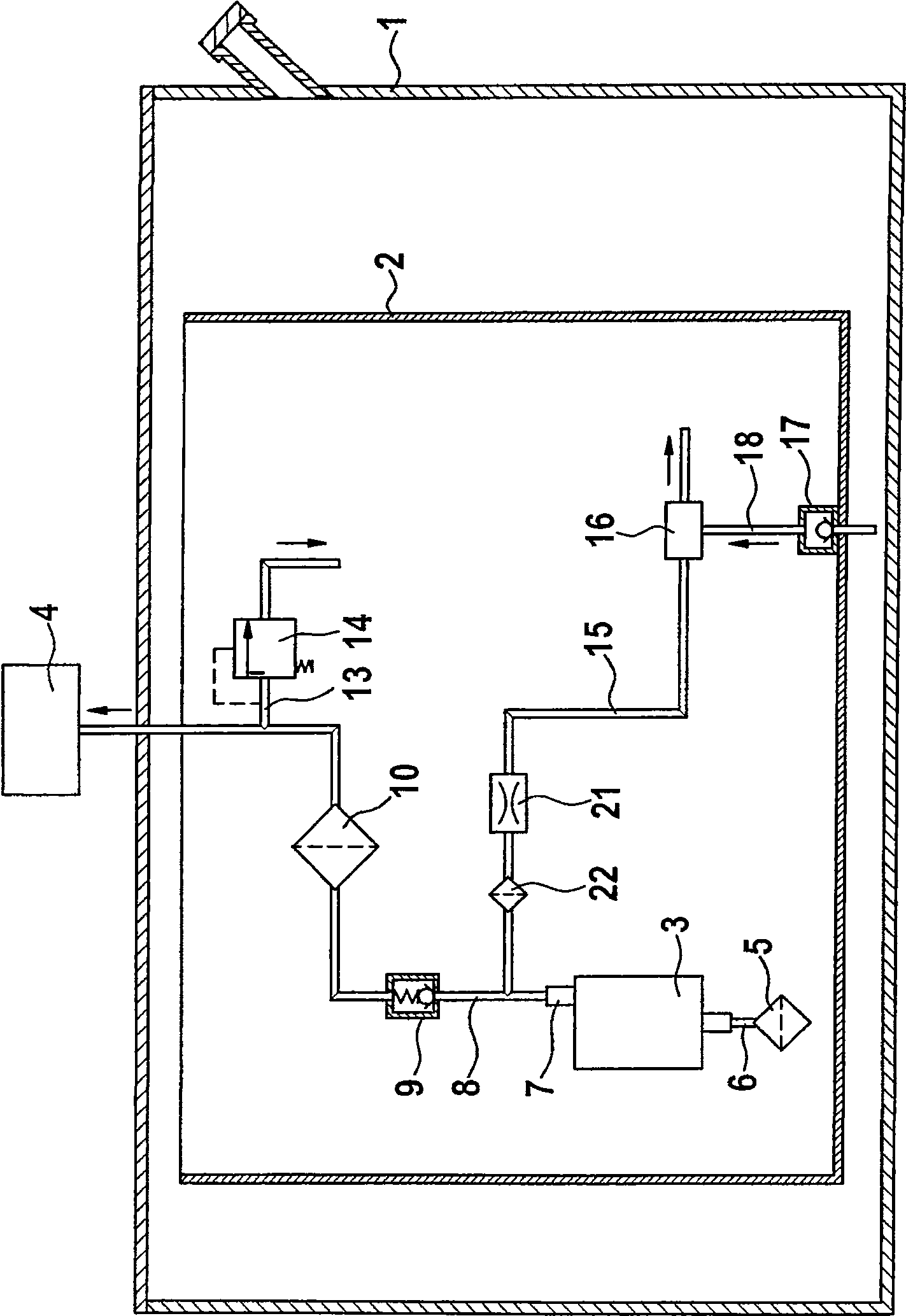
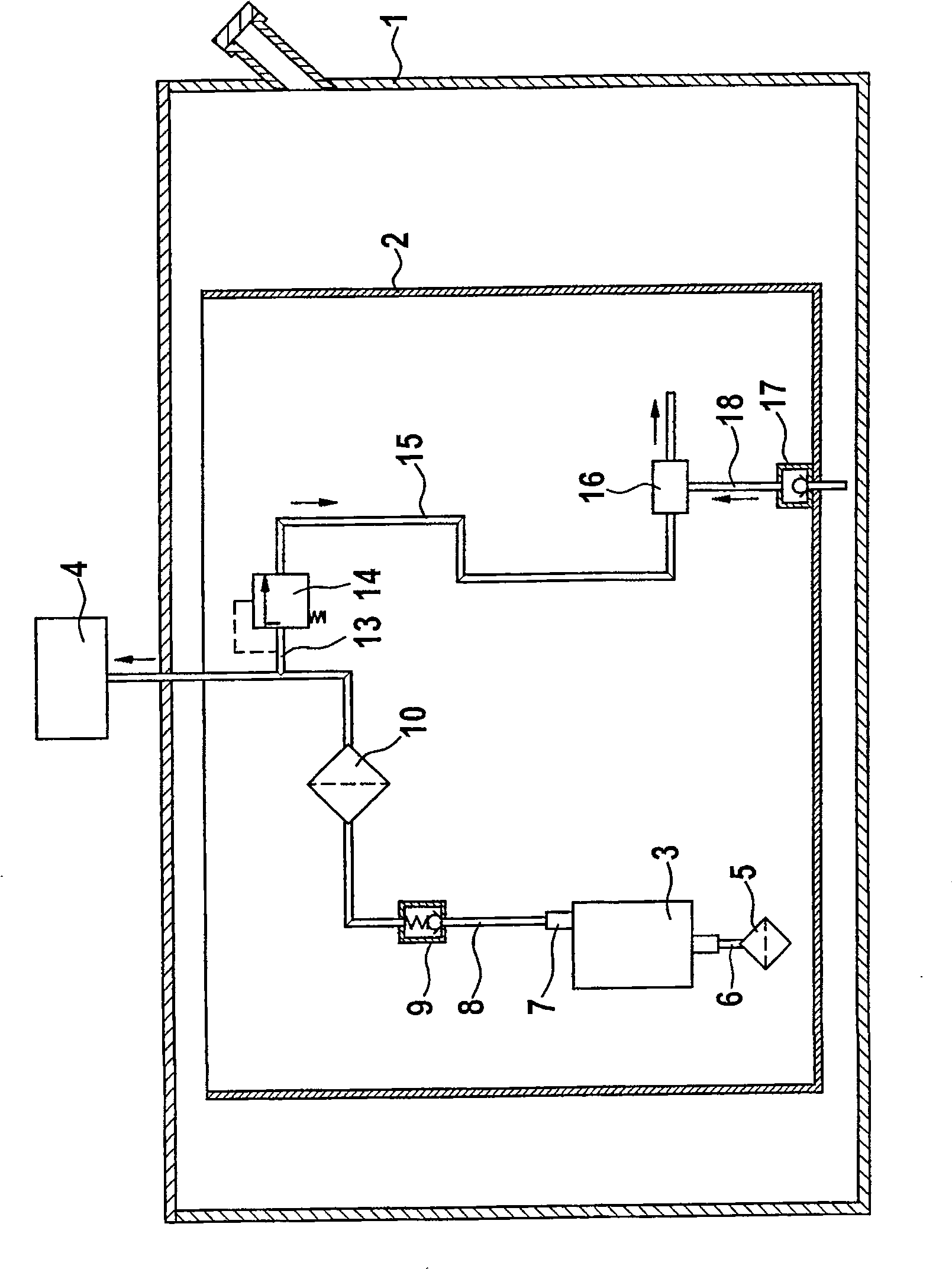
[0018] figure 1 A device for conveying fuel according to a first embodiment is shown schematically.

[0019] The device is used, for example, to feed fuel from a storage container 1 into a storage container 2 and from there via a delivery unit 3 to an internal combustion engine 4 of a motor vehicle.

[0020] A storage container 2 is accommodated in the storage container 1 , and a delivery unit 3 is accommodated in the storage container 2 . Delivery unit 3 is, for example, a vane pump or a displacement pump.

[0021] The storage container 2, for example in the form of a tank, is stored with enough fuel so that no fuel can be fed into the storage container 2, for example due to driving around a curve and the resulting sloshing movement of the fuel in the storage container 1. The supply of fuel to the internal combustion engine 4 via the delivery unit 3 is ensured.

[0022] Delivery unit 3 draws fuel from storage container 2 , for example via prefilter 5 and suction line 6 , a...


PUM


Abstract

Known devices for delivering fuel have a delivery unit and a main filter arranged downstream of the delivery unit with a filter housing and a drive line for driving a suction jet pump. A disadvantage is that the drive line has to be assembled in the device as a single piece. As a result, the assembly and manufacturing costs of the device are relatively high. Manufacturing costs are reduced in the device according to the invention. According to the invention, the drive line (15) is constructed on the filter housing (26) of the main filter (10).

Description

technical field [0001] The invention relates to a device for delivering fuel from a storage container to an internal combustion engine. Background technique [0002] A device for delivering fuel has been known from EP 0 959 242 B1, which has a delivery unit, a main filter with a filter housing arranged downstream of the delivery unit and a pump for driving the suction Drive lines for jet pumps. A disadvantage is that the drive line has to be assembled in the device as a single piece. As a result, the assembly and manufacturing costs of the device are relatively high. Contents of the invention [0003] According to the invention, a device for delivering fuel from a storage tank to an internal combustion engine is proposed, which has a delivery unit, a main filter arranged in a filter housing downstream of the delivery unit, and a A drive line of the suction jet pump, wherein: the drive line is configured on the filter housing of the main filter. [0004] In contrast, th...

Claims


Application Information

Patent Timeline
Patent Type & Authority Patents(China)
IPC IPC(8): B60K15/077F02M37/10F02M37/00F02M37/02
CPCF02M37/106B60K2015/03105F02M37/025B60K2015/03236B60K15/077F02M37/0058F02M37/10
Inventor 汉斯-彼得·布劳恩托马斯·威兰彼得·西梅克帕维尔·莫特卡
Owner ROBERT BOSCH GMBH
Features
  • Generate Ideas
  • Intellectual Property
  • Life Sciences
  • Materials
  • Tech Scout
  • Unparalleled Data Quality
  • Higher Quality Content
  • 60% Fewer Hallucinations
Learn More