Air-fuel ratio control system for internal combustion engine

A technology of control device and air-fuel ratio, which is applied in engine control, fuel injection device, fuel injection control, etc., can solve problems such as inability to obtain, and achieve the effect of maintaining control performance

Inactive Publication Date: 2009-07-29
HONDA MOTOR CO LTD
View PDF8 Cites 0 Cited by
  • Summary
  • Abstract
  • Description
  • Claims
  • Application Information

AI Technical Summary

Problems solved by technology

That is, the overshoot of the air-fuel ratio control signal SCTL is improved, but it cannot be obtained Figure 21 The normal air-fuel ratio control signal SCTL shown by the dotted line L3 in (a)

Method used


Image

  • Air-fuel ratio control system for internal combustion engine
  • Air-fuel ratio control system for internal combustion engine
  • Air-fuel ratio control system for internal combustion engine

Examples


Embodiment Construction

[0035] Hereinafter, embodiments of the present invention will be described with reference to the drawings.

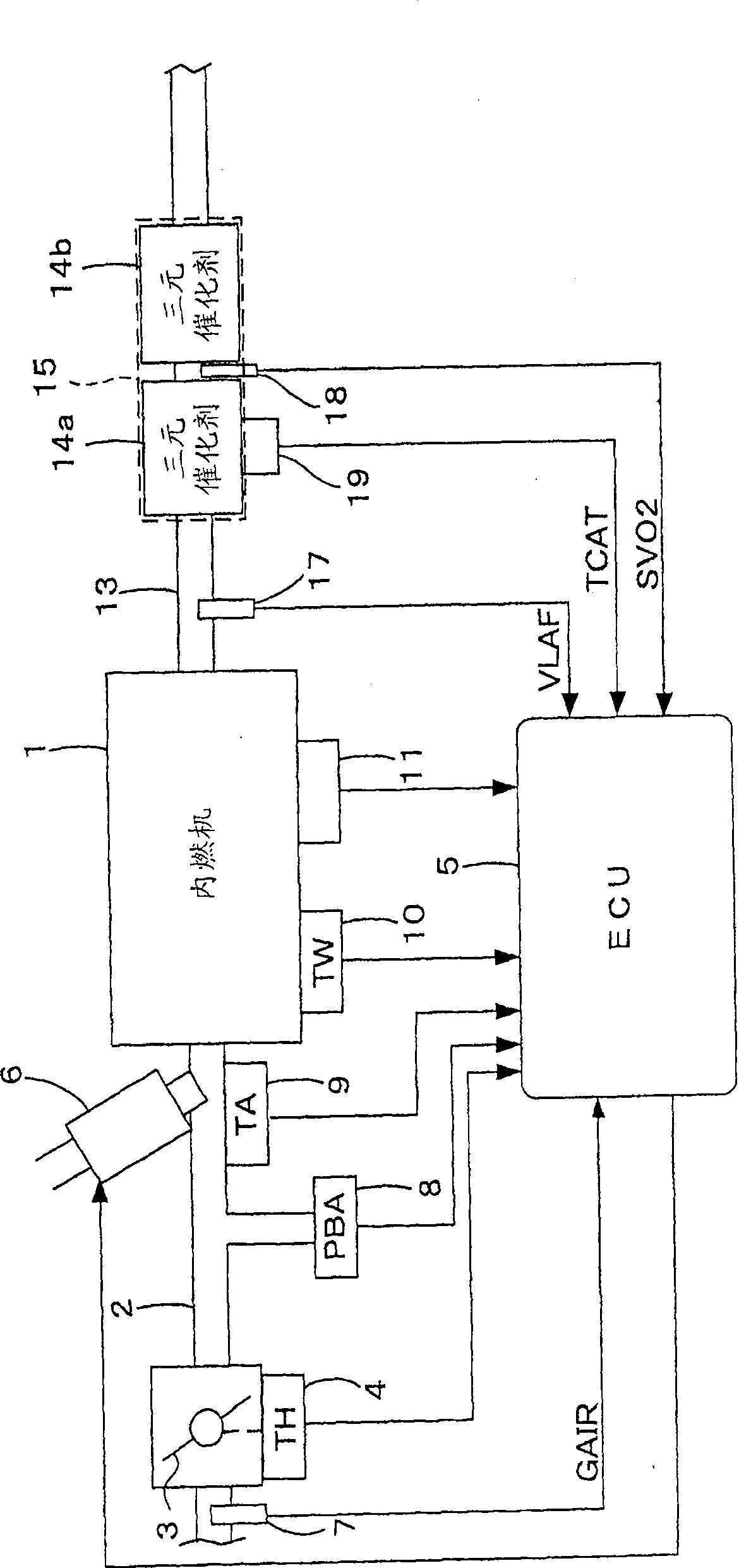
[0036] figure 1 It is an overall configuration diagram of an internal combustion engine (hereinafter referred to as "engine") and its air-fuel ratio control device according to an embodiment of the present invention, and a throttle valve 3 is disposed in the middle of an intake pipe 2 of, for example, a 4-cylinder engine 1 . A throttle opening (TH) sensor 4 is connected to the throttle valve 3 , outputs an electrical signal corresponding to the opening of the throttle valve 3 , and supplies it to an electronic control unit (hereinafter referred to as “ECU”) 5 .

[0037] The fuel injection valve 6 is arranged for each cylinder, and is arranged between the engine 1 and the throttle valve 3 and slightly upstream of the intake valve (not shown) of the intake pipe 2. The pump is connected and electrically connected to the ECU 5 , and the opening timing of the fuel injectio...


PUM


Abstract

An air-fuel ratio control system for an internal combustion engine having a catalyst (14a,14b) provided in an exhaust system of the engine for purifying exhaust gases and a first oxygen concentration sensor (17) disposed upstream of the catalyst is disclosed. The air-fuel ratio control system controls an air-fuel ratio of an air-fuel mixture supplied to the engine. A degree of response deterioration of the first oxygen concentration sensor is detected. A response delay of the first oxygen concentration sensor is compensated according to the detected degree of deterioration to calculate a compensated sensor output. The air-fuel ratio is controlled so that a detected air-fuel ratio calculated from the compensated sensor output coincides with a target air-fuel ratio. A frequency characteristic of the compensation is adjusted according to the detected degree of deterioration.

Description

technical field [0001] The present invention relates to an internal combustion engine air-fuel ratio control device, and more particularly to an internal combustion engine air-fuel ratio control device having a function of judging the deterioration of the characteristics of an oxygen concentration sensor provided in an exhaust system. Background technique [0002] Patent Document 1 discloses a method of judging the deterioration of the oxygen concentration sensor based on the output of the oxygen concentration sensor when the fuel supply cut-off operation of the internal combustion engine is started or when the fuel supply is restarted. , the control gain of the air-fuel ratio feedback control corresponding to the output of the oxygen concentration sensor is adjusted. [0003] More specifically, the control gain of the air-fuel ratio feedback control is adjusted so that the greater the degree of deterioration of the oxygen concentration sensor, the smaller. [0004] [Patent...

Claims


Application Information

Patent Timeline
Patent Type & Authority Patents(China)
IPC IPC(8): F02D41/14F02D41/22F02D45/00
CPCF01N2560/025F01N2900/0422F01N2560/14Y02T10/47F02D41/182Y02T10/22F02D41/1441F01N3/101F02D2041/1431F02D41/1456F01N3/0864F01N2560/06F02M69/044F02D41/1495F01N11/007F02D2200/0816Y02T10/12Y02T10/40
Inventor 饭田润牧秀隆末广幸夫
Owner HONDA MOTOR CO LTD
Why Eureka
Try Eureka