Air-fuel ratio control system for internal combustion engine

A control device and air-fuel ratio technology, applied in engine control, fuel injection device, fuel injection control, etc., can solve the problem of not being able to obtain the air-fuel ratio control signal SCTL, and achieve the effect of maintaining control performance

Inactive Publication Date: 2007-10-10
HONDA MOTOR CO LTD
View PDF1 Cites 14 Cited by
  • Summary
  • Abstract
  • Description
  • Claims
  • Application Information

AI Technical Summary

Problems solved by technology

That is, the overshoot of the air-fuel ratio control signal SCTL is improved, but the normal air-fuel ratio control signal SCTL shown by the dotted line L3 in FIG. 21( a ) cannot be obtained.

Method used


Image

  • Air-fuel ratio control system for internal combustion engine
  • Air-fuel ratio control system for internal combustion engine
  • Air-fuel ratio control system for internal combustion engine

Examples


Embodiment Construction

[0035] Hereinafter, embodiments of the present invention will be described with reference to the drawings.

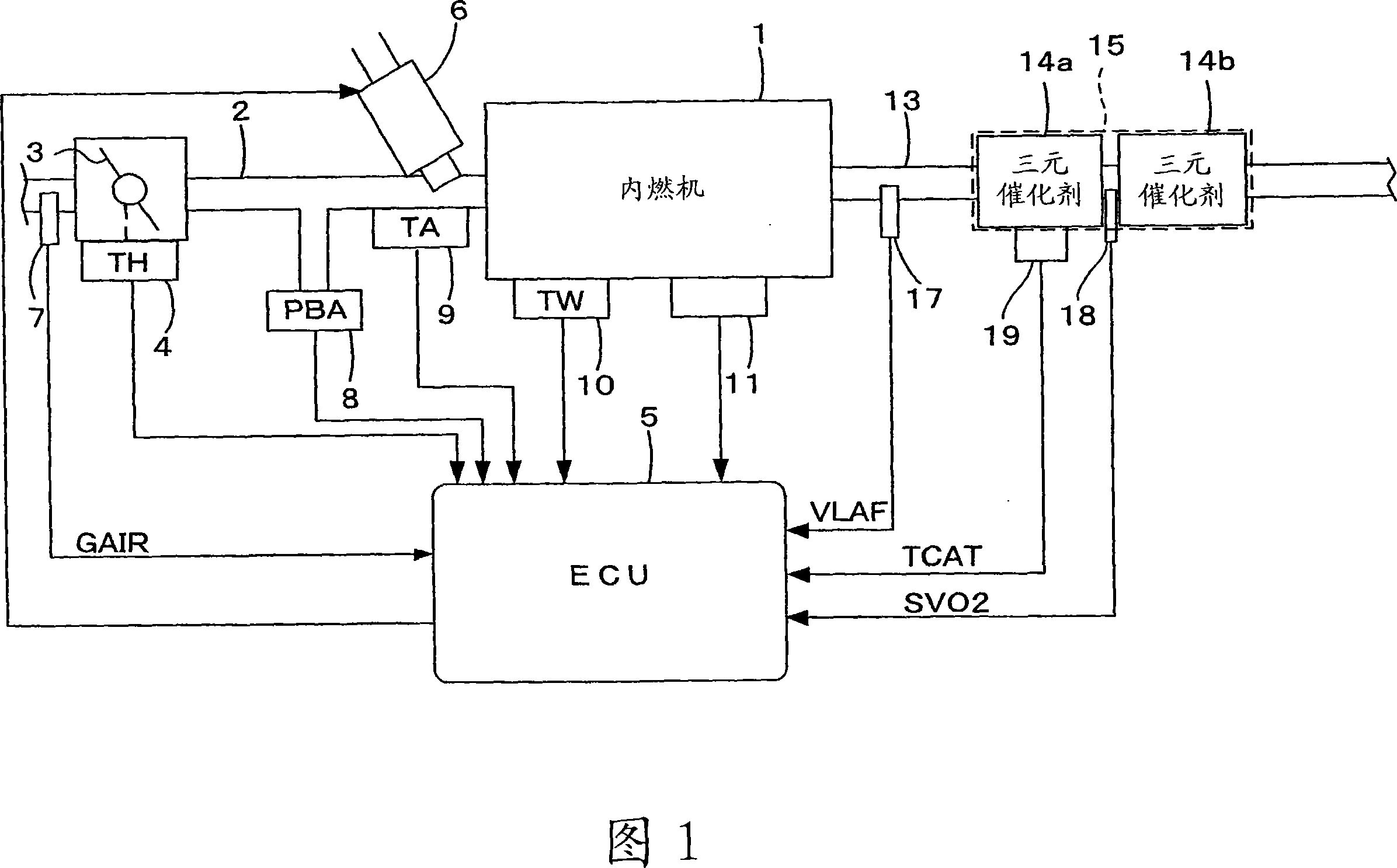
[0036] 1 is an overall configuration diagram of an internal combustion engine (hereinafter referred to as "engine") and its air-fuel ratio control device according to an embodiment of the present invention. A throttle valve 3 is disposed in the middle of an intake pipe 2 of, for example, a 4-cylinder engine 1 . A throttle opening (TH) sensor 4 is connected to the throttle valve 3 , outputs an electrical signal corresponding to the opening of the throttle valve 3 , and supplies it to an electronic control unit (hereinafter referred to as “ECU”) 5 .

[0037] The fuel injection valve 6 is arranged for each cylinder, and is arranged between the engine 1 and the throttle valve 3 and slightly upstream of the intake valve (not shown) of the intake pipe 2. The pump is connected and electrically connected to the ECU 5 , and the opening timing of the fuel injection valve 6 is con...


PUM


Abstract

An air-fuel ratio control system for an internal combustion engine having a catalyst provided in an exhaust system of the engine for purifying exhaust gases and a first oxygen concentration sensor disposed upstream of the catalyst is disclosed. The air-fuel ratio control system controls an air-fuel ratio of an air-fuel mixture supplied to the engine. A degree of response deterioration of the first oxygen concentration sensor is detected. A response delay of the first oxygen concentration sensor is compensated according to the detected degree of deterioration to calculate a compensated sensor output. The air-fuel ratio is controlled so that a detected air-fuel ratio calculated from the compensated sensor output coincides with a target air-fuel ratio. A frequency characteristic of the compensation is adjusted according to the detected degree of deterioration.

Description

technical field [0001] The present invention relates to an internal combustion engine air-fuel ratio control device, and more particularly to an internal combustion engine air-fuel ratio control device having a function of judging the deterioration of the characteristics of an oxygen concentration sensor provided in an exhaust system. Background technique [0002] Patent Document 1 discloses a method of judging the deterioration of the oxygen concentration sensor based on the output of the oxygen concentration sensor when the fuel supply cut-off operation of the internal combustion engine is started or when the fuel supply is restarted. , the control gain of the air-fuel ratio feedback control corresponding to the output of the oxygen concentration sensor is adjusted. [0003] More specifically, the control gain of the air-fuel ratio feedback control is adjusted so that the greater the degree of deterioration of the oxygen concentration sensor, the smaller. [0004] [Patent...

Claims


Application Information

Patent Timeline
Patent Type & Authority Applications(China)
IPC IPC(8): F02D41/14F02D41/22F02D45/00
CPCF01N3/101F02D41/1495F01N2560/025F01N3/0864F02M69/044F02D41/182F01N11/007F02D2200/0816Y02T10/47Y02T10/22F02D2041/1431F02D41/1441F01N2560/06F01N2560/14F01N2900/0422F02D41/1456Y02T10/12Y02T10/40
Inventor 饭田润牧秀隆末广幸夫
Owner HONDA MOTOR CO LTD
Why Eureka
Try Eureka