Motor-adjustable steering column for a motor vehicle

a motor vehicle and steering column technology, applied in the direction of steering parts, vehicle components, transportation and packaging, etc., can solve the problems of reducing the rigidity of the actuating unit and the natural frequency of the steering column, unacceptable, and the known motor-adjustable steering column is not suitable for automatic stowage of the steering column. achieve the effect of high adjustment acceleration

Active Publication Date: 2019-01-31
THYSSENKRUPP PRESTA AG +1
View PDF0 Cites 14 Cited by
  • Summary
  • Abstract
  • Description
  • Claims
  • Application Information

AI Technical Summary

Benefits of technology

[0032]One advantageous embodiment of the invention provides that the operating element may, by pivoting the actuating unit about the pivot pin, be brought into active engagement with the supporting unit to set the release position, i.e. to switch over into or out of the release position. In this case, the operating element is arranged on the outer casing tube such that it strikes against the supporting unit in a particular height position of the height adjustment and is thereby operated. The above-stated height position forms a switchover position, which is located outside the use range of the steering column and which is passed on stowage in the vertical direction prior to reaching or on reaching the vertical stowage position, which is conventionally located in the upper range of the maximum vertical adjusting height. In this case, the friction means is switched over from the friction into the release position, such that the casing tubes may be retracted by the then reduced frictional force with a high adjustment acceleration and adjustment speed in the longitudinal direction from the comfort position range into the stowage position. If the actuating

Problems solved by technology

Reducing the frictional force to the necessary extent for this purpose by increasing play between the casing tubes would however reduce the rigidity of the actuating unit and the natural frequency of the steering column, which i

Method used


Image

  • Motor-adjustable steering column for a motor vehicle
  • Motor-adjustable steering column for a motor vehicle
  • Motor-adjustable steering column for a motor vehicle

Examples


Embodiment Construction

[0054]In the various figures identical parts are always provided with the same reference signs and are therefore as a rule also respectively only named or mentioned once.

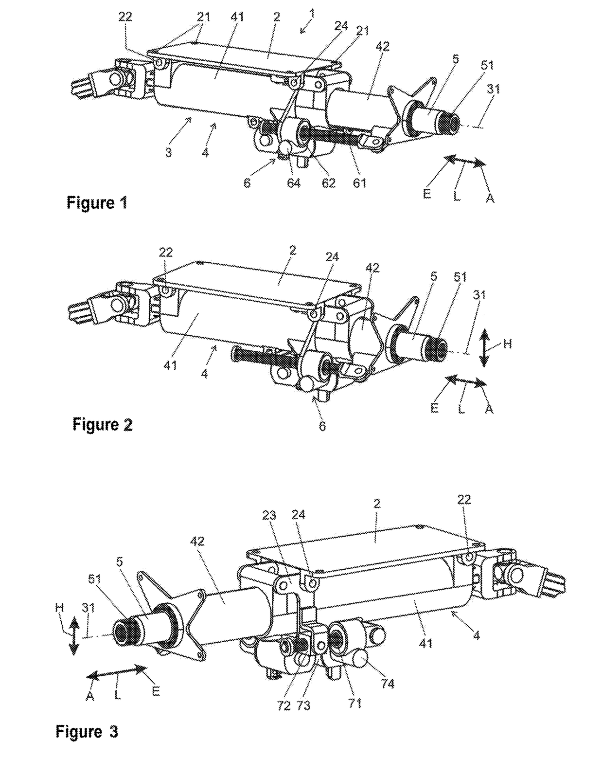
[0055]FIGS. 1, 2 and 3 are schematic, perspective views of a steering column 1 according to the invention, obliquely from above and to the side onto the rear end, based on the direction of travel of a vehicle, not shown. FIG. 2 shows the fully retracted or pulled-in state corresponding to the stowage position in the longitudinal direction. FIGS. 1 and 3 show the extended or extracted state, corresponding to a longitudinal position within the comfort position range, from the left-hand side (FIG. 1) and from the right-hand side (FIG. 3). A longitudinal position within the comfort position range is hereinafter also designated a comfort position or comfort setting.

[0056]The steering column 1 comprises a supporting unit 2, which comprises fastening means 21 for connection with a motor vehicle body, not shown. The support...


PUM


Abstract

A motor-adjustable steering column including a supporting unit which is connectable to a vehicle body and by which an actuating unit is held which includes a steering spindle mounted in a casing unit to be rotatable about a longitudinal axis. The casing unit has an outer casing tube, in which an inner casing tube is accommodated to be axially displaceable telescopically in the direction of the longitudinal axis. An actuating drive is connected to the inner casing tube and the outer casing tube by which the inner casing tube may be displaced axially in and out relative to the outer casing tube. A feature arranged between the outer casing tube and the inner casing tube generates a frictional force between outer casing tube and inner casing tube with regard to relative displacement which is adjustable between a release position and at least one friction position.

Description

BACKGROUND OF THE INVENTION[0001]The invention relates to a motor-adjustable steering column for a motor vehicle, comprising a supporting unit which is connectable with a vehicle body and by which an actuating unit is held which comprises a steering spindle mounted in a casing unit so as to be rotatable about a longitudinal axis, the casing unit having an outer casing tube, in which an inner casing tube is accommodated so as to be axially displaceable telescopically in the direction of the longitudinal axis, and having an actuating drive, which is connected with the inner casing tube and the outer casing tube and by which the inner casing tube may be displaced axially in and out relative to the outer casing tube.[0002]Steering columns for motor vehicles comprise a steering shaft with a steering spindle, to whose rear end in the direction of travel, facing the driver, a steering wheel is attached for the introduction of a steering command by the driver. The steering spindle is rotata...

Claims


Application Information

Patent Timeline
IPC IPC(8): B62D1/181B62D1/185B62D1/184B62D1/183
CPCB62D1/181B62D1/185B62D1/184B62D1/183
Inventor HUBER, SEBASTIAN
Owner THYSSENKRUPP PRESTA AG
Why Eureka
Try Eureka