Switch device

A technology for switch devices and switch parts, which is applied in the direction of electric switches, electrical components, household components, etc. It can solve the problems that sliding components cannot move, only a single switching contact can be configured, and the amount of operation is small, so as to achieve improved operability and large operation. Quantity, easy to use effect

Inactive Publication Date: 2009-08-05
ALPS ALPINE CO LTD
View PDF5 Cites 2 Cited by
  • Summary
  • Abstract
  • Description
  • Claims
  • Application Information

AI Technical Summary

Problems solved by technology

[0012] However, in the above-mentioned conventional switch device, since a part of the slide member is guided in a direction perpendicular to the movable contact by the inclined piece provided on the cover body, the slide member cannot be moved further after the switch is switched. Mobile, so there is a small amount of operation, and only a single switching contact can be configured

Method used


Image

  • Switch device
  • Switch device
  • Switch device

Examples


Embodiment Construction

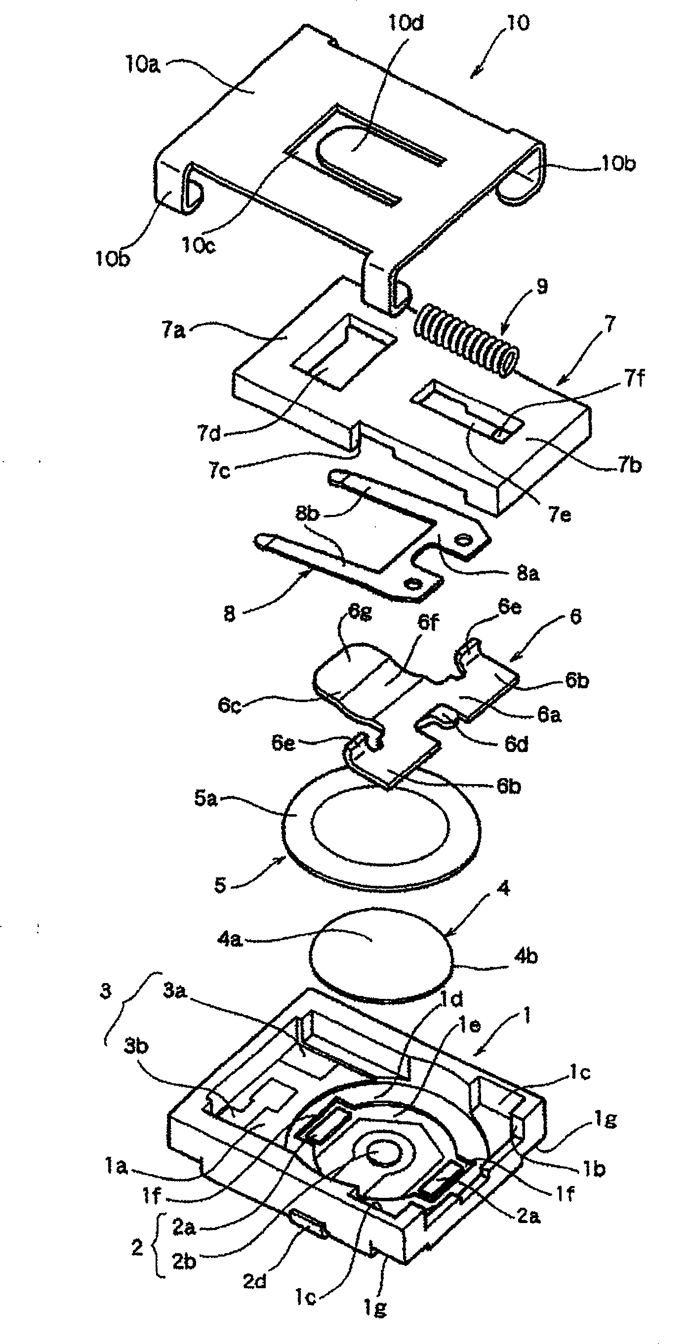
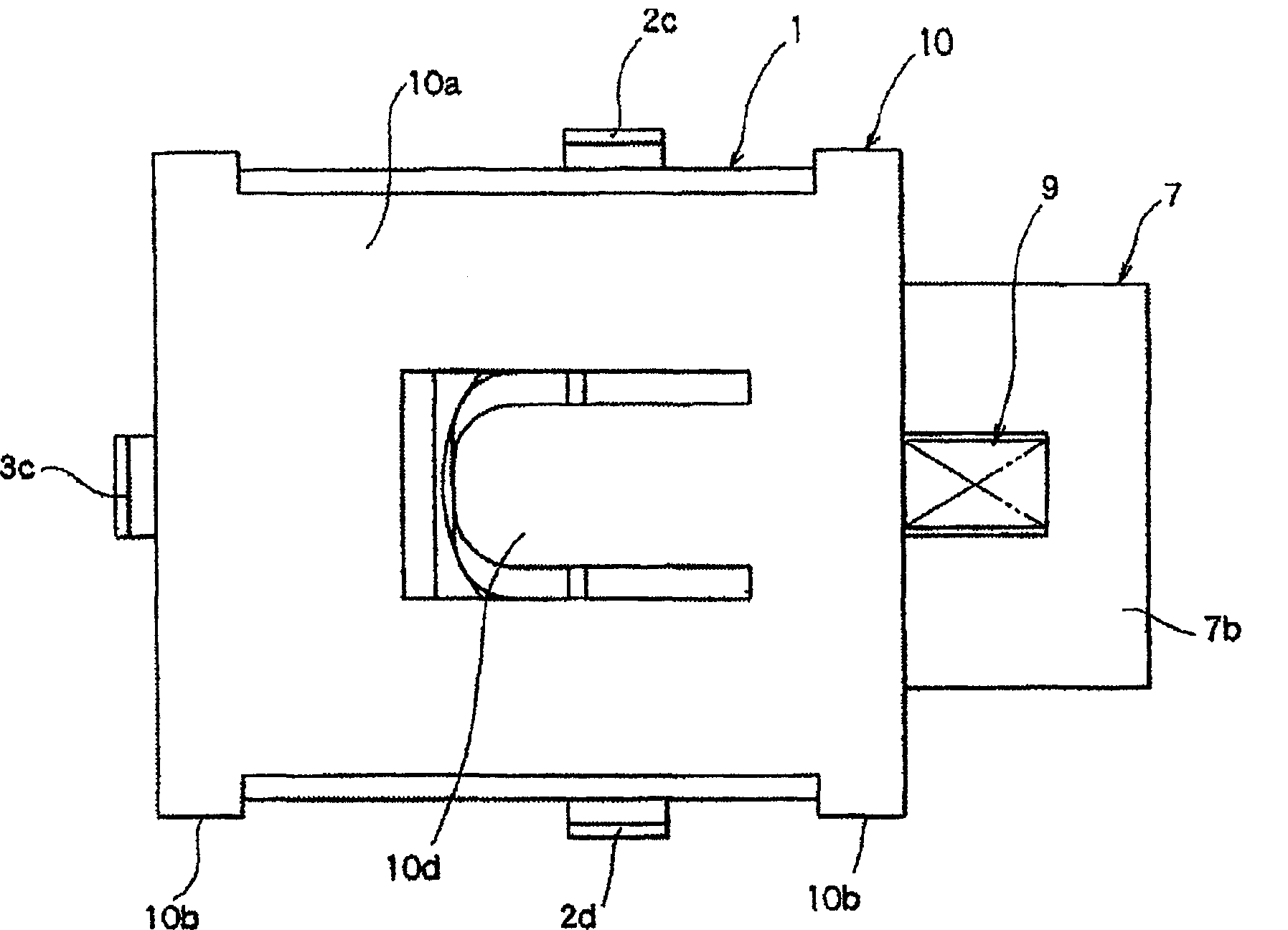
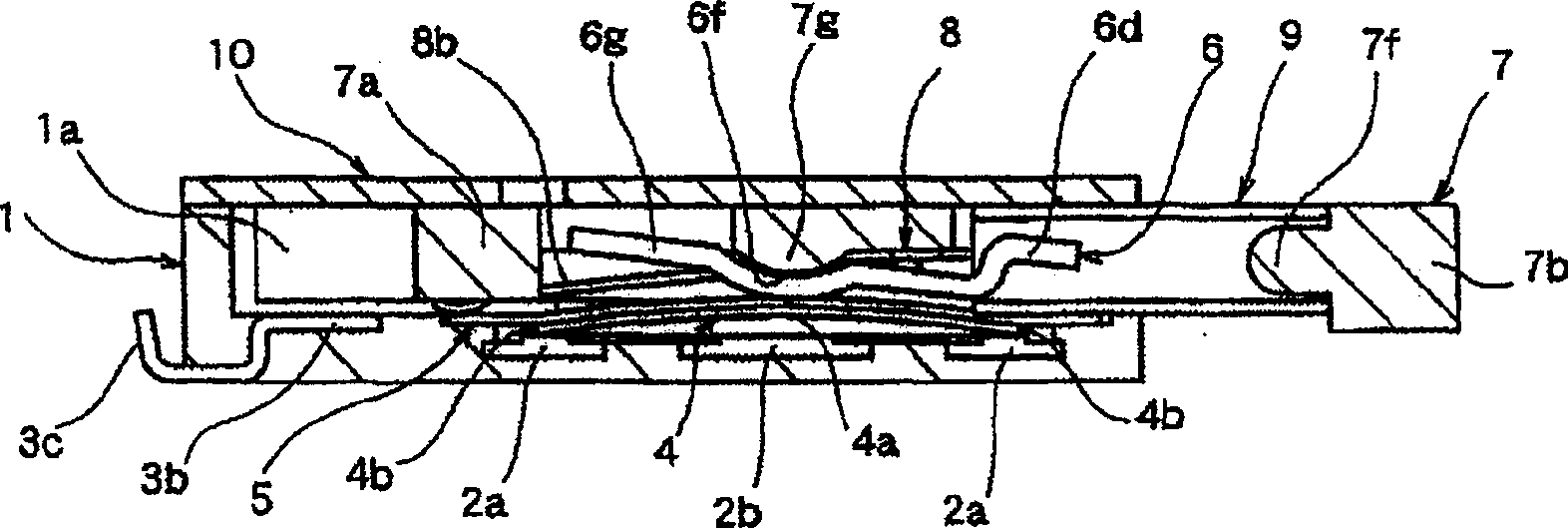
[0034] the following, Figure 1 to Figure 6 Embodiments of the present invention are shown. figure 1 It is an exploded perspective view showing the switchgear of the present invention, figure 2 It is a plan view showing the switchgear of the present invention, image 3 It is a sectional view showing the initial state of the switchgear of the present invention, Figure 4 It is a cross-sectional view showing the first stage of the switching device of the present invention, Figure 5 It is a sectional perspective view of main parts showing the state of the switchgear of the present invention with the cover removed, Image 6 It is a bottom view showing the assembled state of the drive unit of the switchgear of the present invention.

[0035] Such as figure 1 As shown, the switch device of the present invention mainly includes: a base 1 having an opening and configured with a plurality of fixed contacts 2, 3; a movable contact 4 and a sliding contact 8 that are in contact w...


PUM


Abstract

To provide an easy-to-use switching device which enables further movement of a slide member after switching, and secures a large operation amount. The switching device is provided with: a base 1 with a first fixed contact 2 arranged; the slide member 7 housed in the base 1 so as to slide and move; an elastic member 9 for energizing the slide member 7 in one direction; a driving plate 6 which abuts on the slide member 7 and moves in a direction orthogonal to the slide member 7 with movement of the slide member 7 to a sliding direction; and a movable contact 4 which is pressed by the driving plate 6 and contacts with and separates from the first fixed contact 2. The driving plate 6 is arranged between the slide member 7 and the movable contact 4, and is rotatably held on the base 1. The movable contact 4 is pressed by rotation of the driving plate 6, and is in contact with the first fixed contact 2. The driving plate 6 includes a slide part 6g which allows the slide member 7 to further move in the sliding direction in a state wherein contact of the movable contact 4 and the first fixed contact 2 is maintained after the movable contact 4 is pressed.

Description

technical field [0001] The present invention relates to a thin horizontal pressure type switch device used as an operation switch for various electronic devices. Background technique [0002] As a conventional horizontal type switchgear, it is known to have a case having an opening, a fixed contact provided on the inner bottom of the opening, a movable contact disposed on the fixed contact, and a movable contact disposed on the movable contact. And a switchgear composed of a dust-proof plate made of polyimide, an operating member that operates a movable contact through the plate, and a cover that is installed on the upper portion of the housing and covers the opening (for example, refer to Patent Document 1 ). [0003] Figure 7 , Figure 8 Indicates existing switchgear. Figure 7 It is an exploded perspective view of a conventional switchgear, Figure 8 It is a cross-sectional view of an essential part of a conventional switchgear. [0004] In the figure, the fixed cont...

Claims


Application Information

Patent Timeline
Patent Type & Authority Patents(China)
IPC IPC(8): H01H15/16H01H15/10
CPCH01H13/12H01H13/26H01H13/52H01H15/02H01H15/10H01H2231/012
Inventor 佐佐木基成
Owner ALPS ALPINE CO LTD
Why Eureka
Try Eureka