
Method of managing cylinders in a rolling facility and installation for implementing same

Inactive Publication Date: 2012-07-03
SIEMENS VIA METALS TECH
View PDF17 Cites 3 Cited by
  • Summary
  • Abstract
  • Description
  • Claims
  • Application Information

AI Technical Summary

Benefits of technology

[0055]By way of advantage, the method consists in realizing an on-line change-over of the chocks, close to the rolling mill, during the roll change-over operation. Thus, the number of chocks and associated bearings is reduced. For the rolling mill with 5 mill stands already considered, the necessary quantity is 10×2=20 bearings and chocks, to which are added 2 to 3 emergency sets, making a maximum of 20+(3×4)=32 bearings and chocks.
[0056]The method according to the invention permits a large amount of operating flexibility of the rolling mill by allowing the most appropriate rolls for the next rolling campaign to be held ready, prepared for action, on the shuttle device, and the stoppage time of the rolling mill to be limited to the minimum.
[0057]By way of advantage, the installation according to the invention makes very good use of coupling devices allowing a chock to be coupled easily to the end of a roll. In particular, the applicant has developed quick-acting locking / unlocking systems for chocks. Such mounting devices are described, for example, in the document FR-9209477. The use of such coupling devices allows all human intervention to be completely eliminated for the mounting and dismantling operations on the chocks during the change-over of the rolls. Given that such a change-over takes place in the immediate vicinity of the rolling mill, the installation according to the invention which can be entirely automated is much safer.
[0058]In general, the replacement of the rolls of the different mill stands of the rolling mill is realized during a single stoppage of rolling operations. According to the prior art, replacement is realized mill stand by mill stand. In fact, replacements carried out simultaneously on the entirety of the mill stands would pose major risks for safety around the rolling mill. According to the invention, it is accepted that the time necessary for the replacement of the rolls of a mill stand under consideration is increased by adding the stages necessary for the exchange of the chocks between the worn rolls and the new rolls. However, the replacement of the rolls of the next mill stand can begin (stages of moving the corresponding car and extracting the worn rolls out of the next mill stand) while the stages for exchanging the chocks for the mill stand under consideration are in the course of being realized. Apart from the iteration of the stages for exchanging the chocks for the last mill stand of the rolling mill, the time necessary in order to carry out the chock exchange stages can be hidden in a conveniently synchronized overall operation.

Problems solved by technology

Furthermore, such an installation must be particularly simple, easy to maintain, and capable of being realized with a limited investment.

Method used


Image

  • Method of managing cylinders in a rolling facility and installation for implementing same
  • Method of managing cylinders in a rolling facility and installation for implementing same
  • Method of managing cylinders in a rolling facility and installation for implementing same

Examples


Embodiment Construction

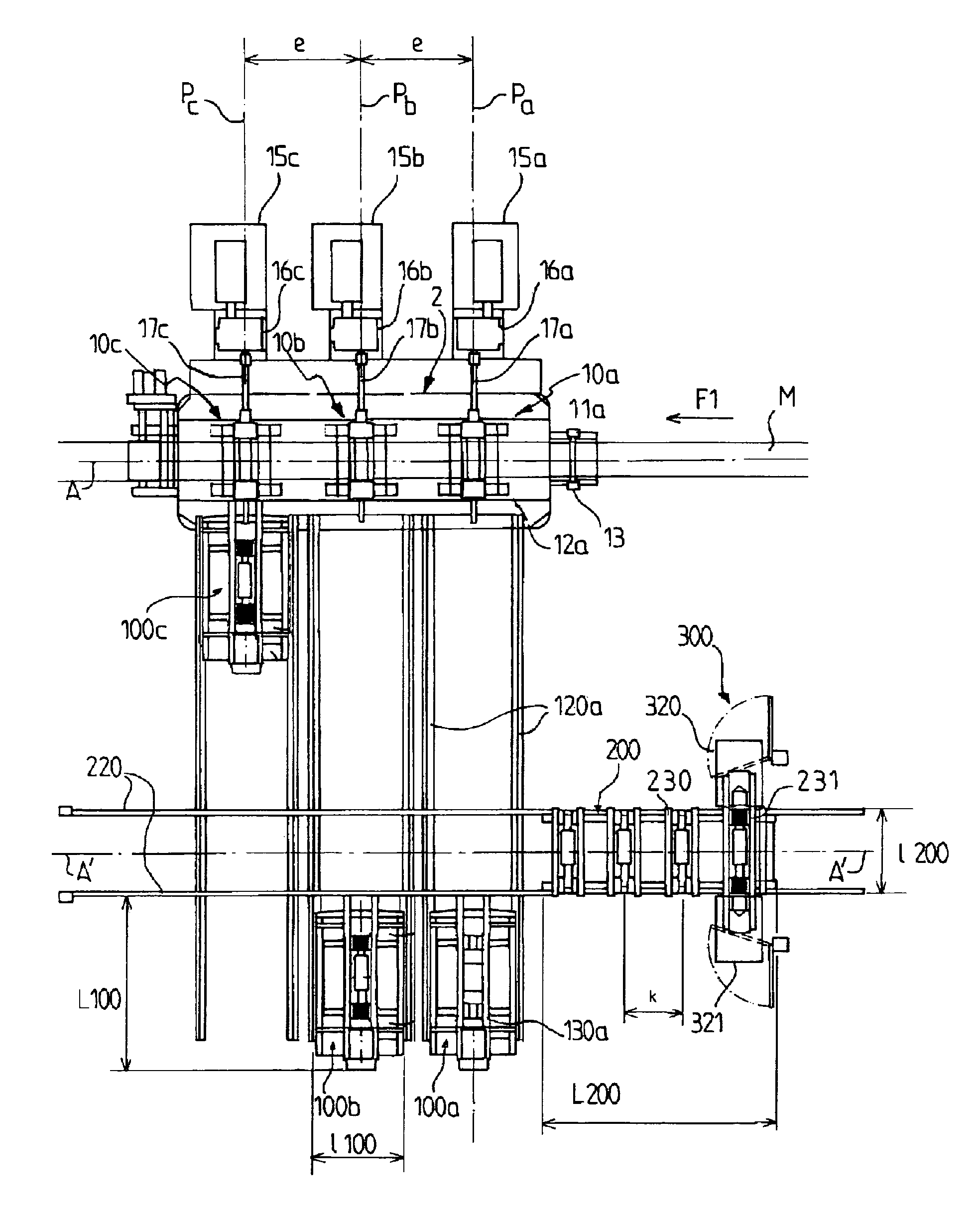
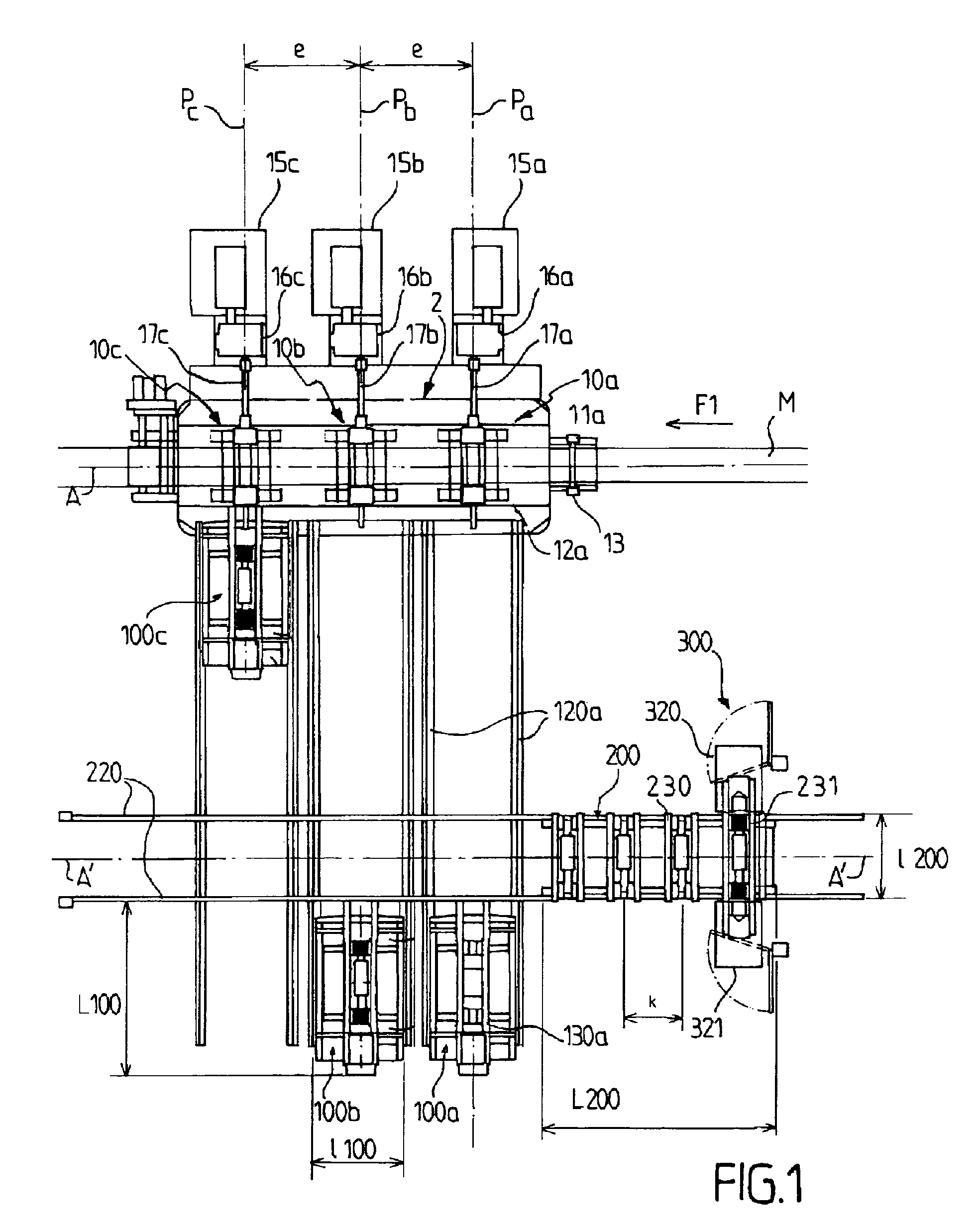
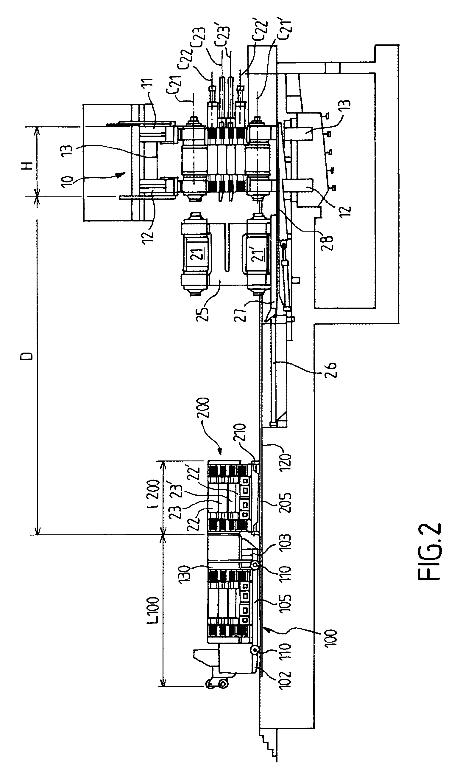
[0063]FIGS. 1 and 2 represent a preferred embodiment of the roll change-over installation according to the invention with which a rolling mill is provided.

[0064]Referring to FIG. 1, a strip of sheet metal M to be rolled is moved along an axis of rolling A in the direction of travel indicated by the arrow F1. The strip M enters the rolling mill 2 on the right of FIG. 1, coming for example from a coil arranged upstream of the rolling mill 2, and exits at the desired thickness on the left of FIG. 1 where it is wound up, for example, on a spindle coiler arranged downstream of the rolling mill 2.

[0065]In the example represented, the rolling mill 2 comprises three mill stands 10a, 10b and 10c, all identical to each other. The three mill stands 10 are arranged in series along the axis of rolling A, with a spacing e.

[0066]As is customary, each mill stand 10 comprises a framework made up of two side pillars 11 and 12, between which the sheet metal M to be rolled passes, joined together by a ...


PUM


Abstract

In a method to replace a pair of rolls of a rolling mill stand during a downtime period, worn rolls fitted with chocks are extracted from the mill stand and positioned on means of displacement that bear a pair of new rolls without chocks. The method sets the means of displacement in motion so that the worn rolls are aligned with a chock extraction device. The chock extraction device is used to remove the chocks from the worn rolls. The means of displacement are actuated so that new rolls are now aligned with the chock extraction device. The chock extraction device is used to reinstall, on the new rolls, the chocks. After the new rolls have been fitted with the chocks, the new rolls are inserted in the mill stand so that the downtime period is reduced and the number of chocks in service is likewise reduced.

Description

CROSS-REFERENCE TO RELATED APPLICATIONS[0001]The present application is a national stage application of International Application No. PCT / FR2006 / 051223, filed on Nov. 23, 2006, which claims priority to French Patent Application No. 0553604, filed on Nov. 25, 2005, which are incorporated herein by reference.BACKGROUND OF THE INVENTION[0002]The invention relates to the field of methods and installations for changing over the rolls of a rolling mill.[0003]During the operation of a rolling mill, the aging of the work rolls that are in contact with the product to be rolled, or that of other rolls such as the intermediate rolls, or again, although less significant, that of the backup rolls, poses a risk of resulting in the production of a defective rolled product or the damaging of the rolls themselves.[0004]Moreover, during a change-over in type of production, it may be necessary to replace a pair of rolls with another pair of rolls having, for example, a different roughness or a differe...

Claims


Application Information

Patent Timeline
IPC IPC(8): B21B31/08B21B31/00
CPCB21B31/103B21B31/10
Inventor ROSSIGNEUX, BERNARD
Owner SIEMENS VIA METALS TECH
Learn More