Brake system for vehicle

a technology for brake systems and vehicles, applied in brake action initiation, brake systems, vehicle components, etc., can solve the problem of reducing the accuracy of braking force to be generated, and achieve the effect of restricting the operation amount of the actuator

Active Publication Date: 2016-02-11
HONDA MOTOR CO LTD
View PDF5 Cites 1 Cited by
  • Summary
  • Abstract
  • Description
  • Claims
  • Application Information

AI Technical Summary

Benefits of technology

[0021]When the brake fluid pressure rises because of the operation of the actuator in the open state of the master-cut valve or the out-valve, the brake fluid of the output side hydraulic system flows into the input side hydraulic system or the reservoir unit. As the operational amount of the actuator is larger, the brake fluid pressure generated by the fluid pressure generating device is higher, so that the amount of the brake fluid flown into the input side hydraulic system or the reservoir unit increases.
[0022]According to this invention, the operational amount of the actuator is restricted. Therefore, the amount of the brake fluid flown into the input side hydraulic system or the reservoir unit is restrained, so that a shortage of the brake fluid of the output side hydraulic system is restrained.

Problems solved by technology

Therefore, the disk brake mechanism is actuated by fluid pressure higher than the brake fluid pressure to be generated by the motor cylinder device, so that there arises a problem that the accuracy of the braking force to be generated decreases.

Method used


Image

  • Brake system for vehicle
  • Brake system for vehicle
  • Brake system for vehicle

Examples


Embodiment Construction

[0032]An embodiment of the present invention will be described in detail with reference to the attached drawings.

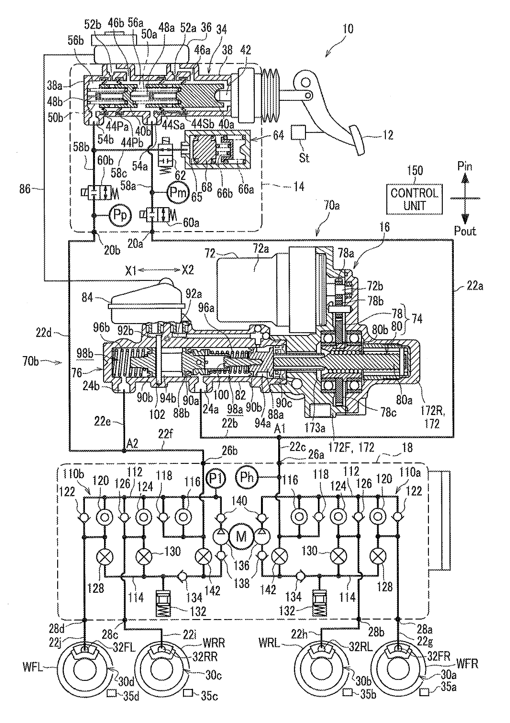
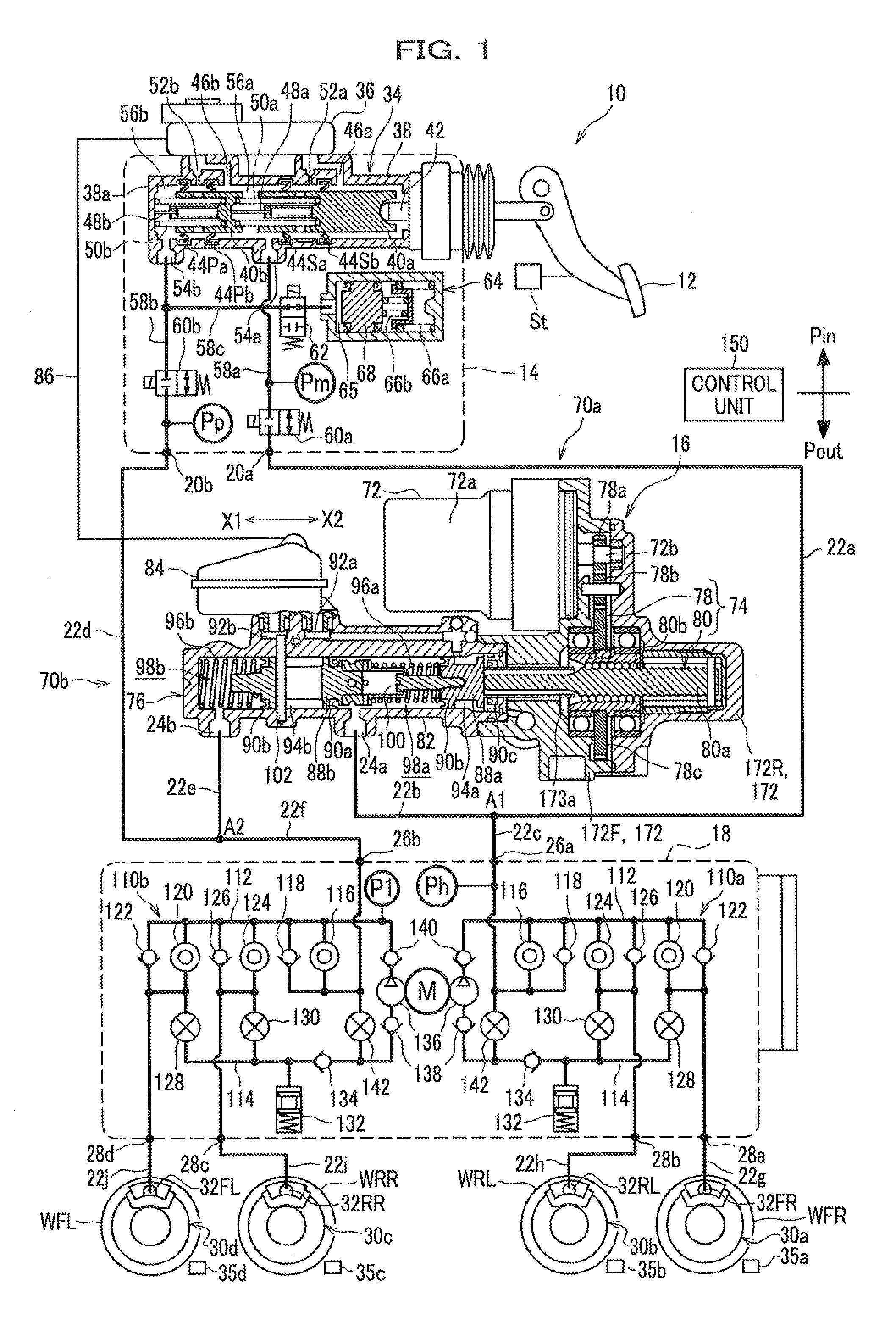
[0033]FIG. 1 is a schematic constitution view of a brake system for a vehicle.

[0034]As shown in FIG. 1, the brake system 10 for a vehicle of this embodiment includes an input device 14, a pedal stroke sensor St, a motor cylinder device 16, and a vehicle movement stability device 18 (Hereinafter, this is referred to as a VSA (vehicle stability assist) device 18. “VSA” is a registered trademark).

[0035]The input device 14 compresses a hydraulic fluid (brake fluid) in accordance with the operational input when an operation piece like a brake pedal 12 is operated by a driver, so that fluid pressure (brake fluid pressure) is generated on the brake fluid in accordance with the operational amount. The pedal stroke sensor St detects the operational amount (pedal stroke) when the brake pedal 12 is pressed down. The motor cylinder device 16 generates operational pressure (brake flui...


PUM


Abstract

Provided is a brake system for a vehicle including an input side hydraulic system, an output side hydraulic system, a first and a second shutoff valves to shut off flowing of the brake fluid between the input side hydraulic system and the output side hydraulic system when closed, a first and a second out-valves through which the brake fluid flows into a reservoir unit when opened, and a control unit to control a motor cylinder device of the output side hydraulic system to generate the brake fluid pressure according to the operational amount of a brake pedal. The control unit opens one or both of the first and the second shutoff valves and the first and the second out-valves when output characteristic of the brake fluid pressure generated by the motor cylinder device shifts from basic characteristic.

Description

CROSS REFERENCE TO RELATED APPLICATION[0001]This application claims the foreign priority benefit under Title 35, United States Code, 119 (a)-(d) of Japanese Patent Application No. 2014-163847 which is filed on Aug. 11, 2014 with the Japan Patent Office, the disclosure of which is herein incorporated by reference in its entirety.BACKGROUND OF THE INVENTION[0002]1. Technical Field[0003]The present invention relates to a brake system for a vehicle.[0004]2. Description of Background Art[0005]In the following patent literature 1, a brake system for a vehicle, which generates frictional braking force by using brake fluid pressure generated by a motor cylinder device (fluid pressure generating device), is described. The motor cylinder device drives a piston (actuator) by using an electric motor to be controlled by a control unit, so that the brake fluid pressure is generated on the brake fluid.[0006]Patent literature 1: Japanese Unexamined Patent Publication No. 2013-075605BRIEF SUMMARY OF...

Claims


Application Information

Patent Timeline
Patent Type & Authority Applications(United States)
IPC IPC(8): B60T13/68B60T8/40B60T13/16
CPCB60T13/686B60T13/167B60T13/162B60T8/4086B60T7/042B60T8/4081B60T13/146B60T13/662B60T13/745
Inventor SHIMADA, TAKASHIUEURA, SOICHIRO
Owner HONDA MOTOR CO LTD
Why Eureka
Try Eureka