Master cylinder

A main body and cylinder technology, applied in the direction of hydraulic brake transmission, etc., can solve problems such as brake fluid supply limitation

Active Publication Date: 2009-08-12
HITACHI LTD
View PDF6 Cites 1 Cited by
  • Summary
  • Abstract
  • Description
  • Claims
  • Application Information

AI Technical Summary

Problems solved by technology

In such a state, the flow of the brake fluid that reaches the communication groove after passing through the gap between the outer peripheral side of the piston oil seal and the bottom of the peripheral groove is hindered by the adhesion of the piston oil seal to the side wall of the groove. As a result, there is The supply of brake fluid is limited and it is necessary to refill it many times

Method used


Image

  • Master cylinder
  • Master cylinder
  • Master cylinder

Examples


Embodiment Construction

[0034] A master cylinder according to an embodiment of the present invention will be described with reference to the drawings.

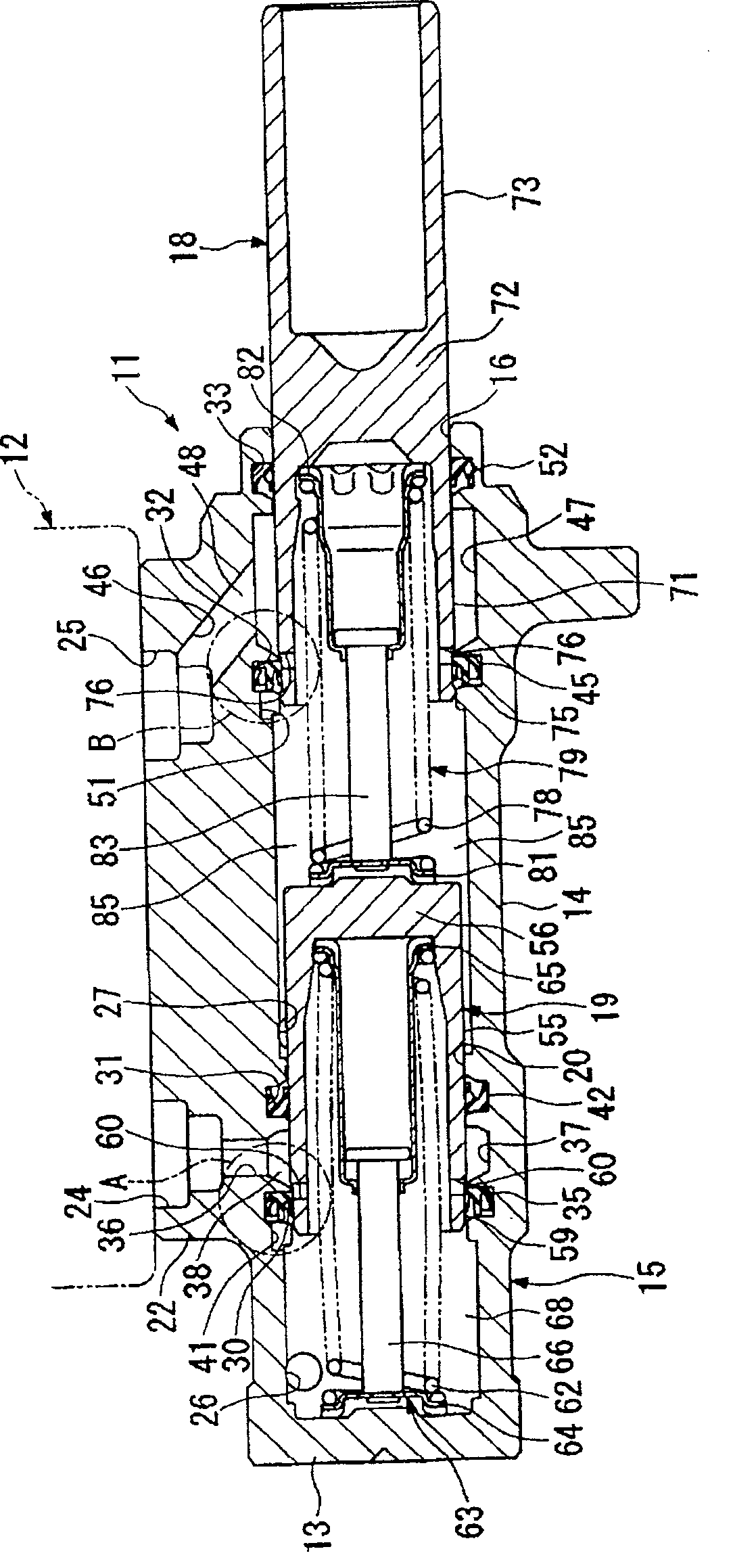
[0035] figure 1 Reference numeral 11 denotes a master cylinder in this embodiment, which generates brake hydraulic pressure by a force corresponding to the operation amount of the brake pedal introduced through a brake booster not shown in the figure. A container 12 for supplying and discharging brake fluid is provided on its upper side.

[0036] The master cylinder 11 is a tandem master cylinder having: a cylinder main body 15 which is processed from one material into a bottomed cylindrical shape having a bottom 13 and a cylinder portion 14, and which is disposed on the vehicle in a transverse posture; a primary piston (piston ) 18 , which is slidably inserted into the opening portion 16 side of the cylinder main body 15 ; The primary piston 18 and the secondary piston 19 are slidably guided on a sliding inner diameter portion 20 having a circular...


PUM


Abstract

A master cylinder that can sufficiently supply brake fluid through the gap between the piston oil seal and the bottom of the peripheral groove and the communication groove when the air is extracted, and as a result, the air can be exhausted with the least number of times. The piston oil seal (35) is installed in the peripheral groove (30) formed on the cylinder main body (15), and can seal between the supply passage (38) communicating with the container and the pressure chamber (68) supplying hydraulic pressure to the discharge passage, It has: an annular base portion (90); an inner peripheral flange portion 91 protruding from the inner peripheral side of the base portion (90) and slidingly contacting the outer peripheral surface of the piston (19); an outer peripheral flange portion (92) extending from the The outer peripheral side of the base (90) protrudes and contacts with the peripheral groove (30) of the cylinder main body (15); the middle protrusion (93) protrudes from the inner peripheral flange portion (91) and the outer peripheral flange portion (92) of the base (90) ) protrudes to the front of the outer peripheral flange portion (92), and a notch groove (95) is formed on the front end side of the intermediate protrusion (93).

Description

technical field [0001] The present invention relates to a master cylinder for supplying brake fluid to a brake device of a vehicle. Background technique [0002] As a conventional master cylinder for supplying brake fluid to the braking device of a vehicle, there is a cylinder in which a sleeve is assembled on the cylinder main body to form a brake fluid discharge path and a supply path; slidably inserted into the cylinder A cover-shaped piston (plunger) that forms a pressure chamber that supplies hydraulic pressure to the discharge path between the cylinder and the cylinder; a piston oil seal that can seal the supply path and the pressure chamber is arranged between the cylinder and the piston, so that when When the cylinder is constructed by assembling the sleeve into the cylinder body, the number of parts naturally increases, and at the same time, the cylinder increases in size in the radial direction. Therefore, it is proposed to abolish the sleeve of the cylinder and in...

Claims


Application Information

Patent Timeline
Patent Type & Authority Patents(China)
IPC IPC(8): B60T11/16
Inventor 毛利友纪镰瀬大五郎甘利泰彦舆水长典
Owner HITACHI LTD
Why Eureka
Try Eureka