Illuminating apparatus

A technology for lighting appliances and appliances, which is applied in lighting devices, lighting auxiliary devices, lighting and heating equipment, etc., and can solve the problem of general products having no structure.

Inactive Publication Date: 2009-08-19
TOSHIBA LIGHTING & TECH CORP
View PDF10 Cites 0 Cited by
  • Summary
  • Abstract
  • Description
  • Claims
  • Application Information

AI Technical Summary

Problems solved by technology

In order to solve the problems existing in lighting fixtures, relevant manufacturers have tried their best to find a solution, but no suitable design has been developed for a long time, and general products do not have a suitable structure to solve the above problems. This is obviously a problem. Issues that relevant industry players are eager to solve

Method used


Image

  • Illuminating apparatus
  • Illuminating apparatus
  • Illuminating apparatus

Examples


Embodiment Construction

[0059] In the following, with reference to the accompanying drawings and preferred embodiments, the specific implementation, structure, features and functions of the lighting fixture proposed according to the present invention will be described in detail as follows.

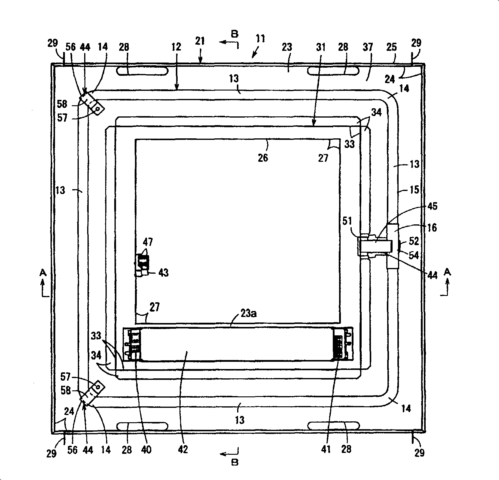
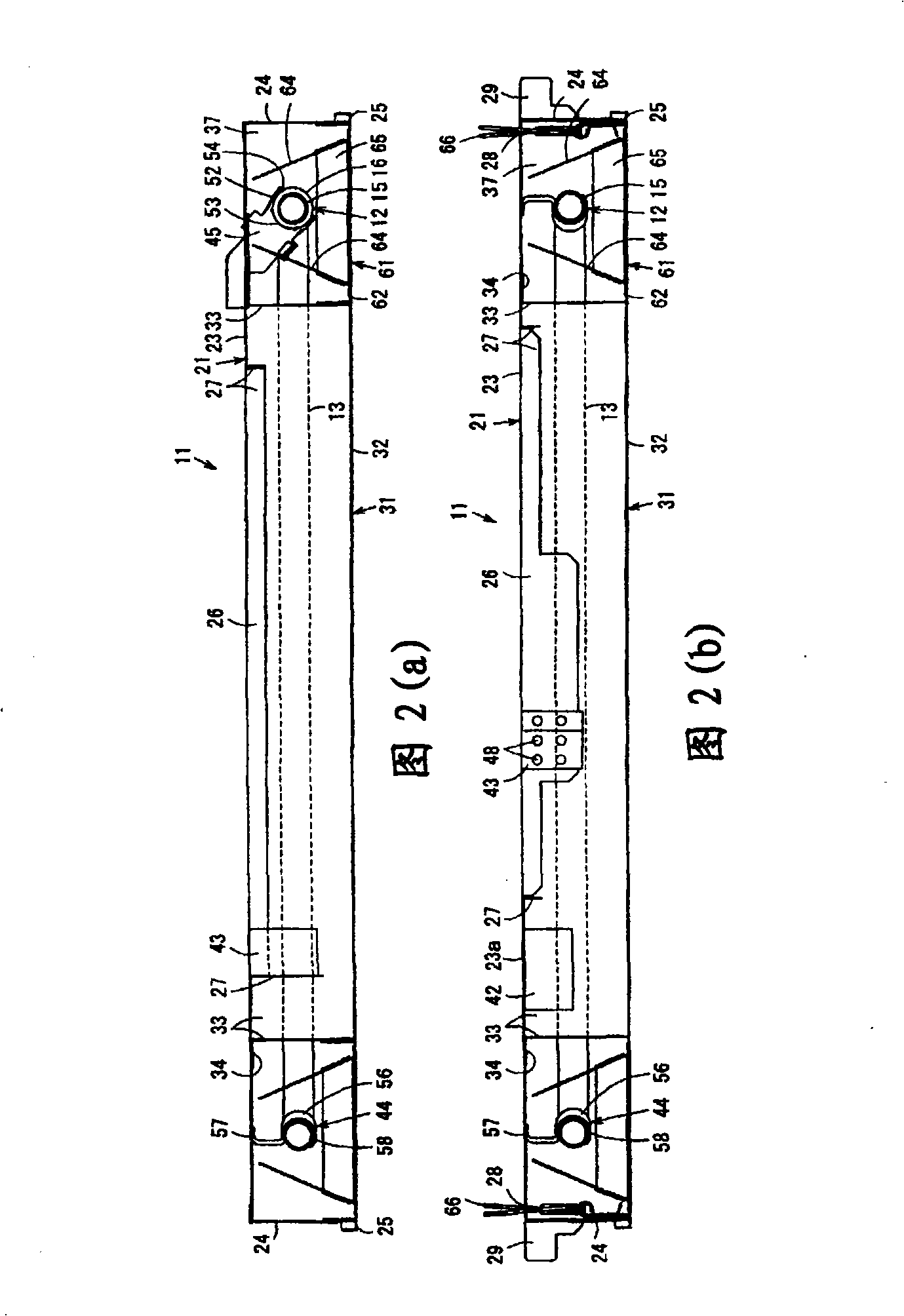
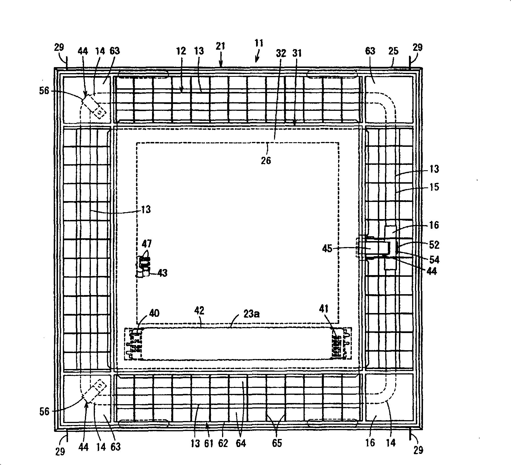
[0060] see Figure 1 to Figure 4 Shown here shows the first embodiment of the present invention. figure 1 It is a sectional bottom view of the ceiling attached equipment installation body of the luminaire, and Fig. 2 is an enlarged sectional view of the luminaire (a) along the figure 1 The cross-sectional view of the A-A line, (b) is along the figure 1 The cross-sectional view of the B-B line, image 3 It is a bottom view of the assembling state of the lighting equipment, Figure 4 It is a bottom view showing the installation of the lamp holder of the lighting fixture.

[0061] exist Figure 1 to Figure 4 Among them, the lighting fixture 11 is, for example, a ceiling-embedded lighting fixture installed in a ...


PUM


Abstract

The invention relates to a lighting appliance, which uses a lamp tube socket provided on the appliance body to support a lamp holder arranged on one side of a quadrangular ring-shaped lamp tube. Two positions including the corners at the two ends of the opposite sides of the lamp cap of the shaped lamp tube. The three parts including the corners of the two parts of the quadrangular annular lamp tube are supported on the appliance body so that the position of the polygonal annular lamp tube is aligned with the central part of the appliance body. The invention can stably support the polygonal annular lamp tube, and can conveniently align the position of the lamp tube with the central part of the device body.

Description

technical field [0001] The invention relates to a lighting appliance, in particular to a lighting appliance using a polygonal annular lamp tube. Background technique [0002] A traditional lighting fixture using a circular lamp tube is provided with a lamp socket that supports the lamp cap of the lamp tube and is electrically connected to it, and a lamp socket that supports the lamp tube at a position opposite to the lamp tube socket. Lamp holder for luminous tubes. Because it is a ring-shaped lamp tube, the position of the ring-shaped lamp tube can be aligned with the central part of the appliance body through the support of the lamp tube socket and the lamp tube bracket at the two opposite parts of the ring-shaped lamp tube. alignment (for example, refer to Patent Document 1). [0003] [Patent Document 1] Japanese Patent Application Laid-Open No. 5-89712 (pp. 2-3, figure 1 ) [0004] But, developed now that the luminous tube is a square ring, and the lamp cap is arrang...

Claims


Application Information

Patent Timeline
Patent Type & Authority Patents(China)
IPC IPC(8): F21V19/00F21V21/108F21Y103/02
Inventor 杉下直树
Owner TOSHIBA LIGHTING & TECH CORP
Why Eureka
Try Eureka