High performance LED lamp system

An LED lamp system and chamber technology, applied in lighting and heating equipment, semiconductor devices of light-emitting elements, flat light sources, etc., can solve problems such as unachieved brightness, and achieve the effect of compact design and high stability

Active Publication Date: 2009-08-19
SIGNIFY HLDG BV
View PDF6 Cites 0 Cited by
  • Summary
  • Abstract
  • Description
  • Claims
  • Application Information

AI Technical Summary

Problems solved by technology

However, currently, the LEDs are not yet bright enough for light projection applications or headlights

Method used


Image

  • High performance LED lamp system
  • High performance LED lamp system
  • High performance LED lamp system

Examples


Embodiment Construction

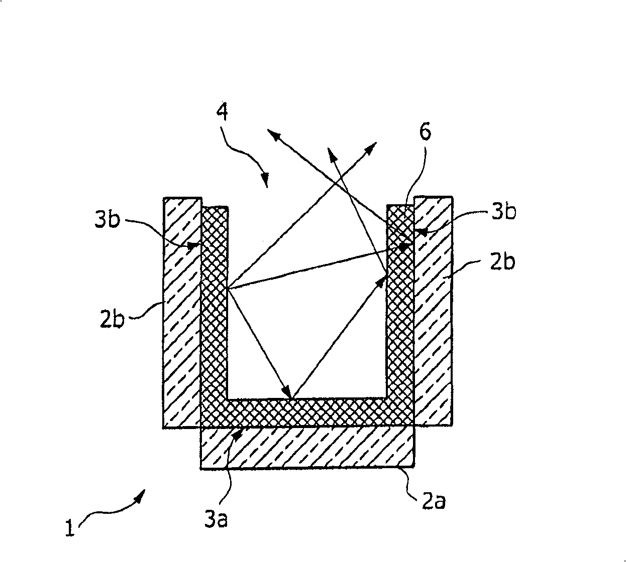
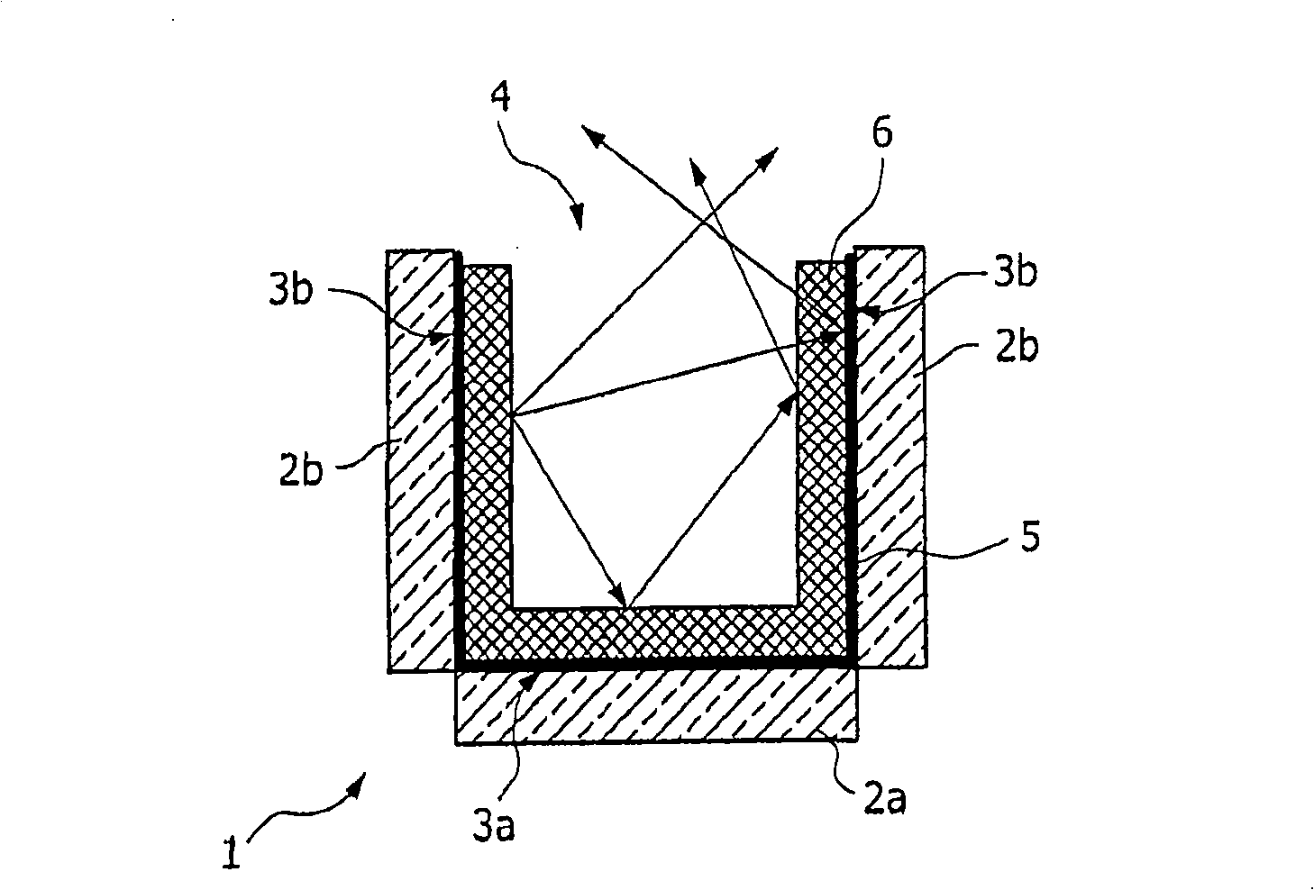
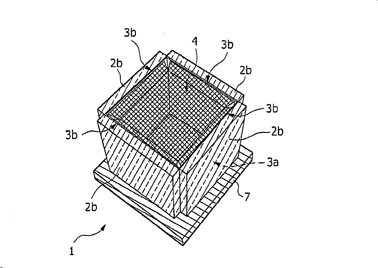
[0031] By means of the example of a cube chamber 1, in a particularly simple embodiment, in Figure 1a The principle on which the microcavity is based is illustrated. A cross-sectional view of a chamber 1 according to the invention formed by three LED elements, 2a, 2b. Their radiating surfaces 3a, 3b form the inner side wall surfaces of the chamber 1 . A phosphor layer 6 is applied on the radiation surfaces 3a, 3b. One side of the chamber 1 serves as a radiation opening 4 .

[0032] Light radiated by one of the LED elements 2 a , 2 b directly enters the fluorescent layer 6 . From there, the light leaves the chamber 1 through the radiation opening 4, possibly after one or more reflections.

[0033] In the chamber 1, light is not only radiated by one LED element, as in the previous design, light is radiated from the LED element 2a and the LED element 2b at right angles thereto on the same surface area. The main consequence of this is that the non-directionally emitted radia...


PUM


Abstract

An LED lamp system with a plurality of LED elements is described. The system comprises a chamber (1) having a plurality of inner side walls and a radiation opening (4) for emitting light. The inner side wall faces are each mainly formed by a plurality of LED radiating surfaces (3a, 3b).

Description

technical field [0001] The invention relates to an LED lamp system with a plurality of LED elements. Background technique [0002] In recent years, the technology for designing and manufacturing inorganic solid-state LEDs has been rapidly improved, reaching a stage of development where inorganic white light-emitting LEDs with efficiencies higher than 40 lm / Watt can be manufactured. This efficiency significantly exceeds the efficiency of traditional incandescent lamps (16lm / Watt), and exceeds the efficiency of most halogen lamps (30-35lm / Watt). At the same time, the efficiency of individual LED elements increases to levels significantly above 100 lm / Watt. [0003] A problem that will affect the widespread availability of LEDs for lighting now and in the future is the still relatively limited amount of light per LED element. For this LED lamp system, an increase in performance can only be achieved if it is possible to combine the light quantities of several LED elements. Al...

Claims


Application Information

Patent Timeline
Patent Type & Authority Patents(China)
IPC IPC(8): H01L33/00F21K99/00
CPCH01L25/0753H01L2924/0002F21K9/00F21K9/62F21K9/64F21Y2105/10H01L2924/00
Inventor J·A·舒格J·L·A·M·索马尼G·鲁特根斯
Owner SIGNIFY HLDG BV
Why Eureka
Try Eureka