
Nail box of nailing machine

A technology for nailing machines and nail magazines, applied in nailing tools, manufacturing tools, etc., which can solve the problems of increased weight, cost, and overall weight of nail magazines, and achieves the effects of cost suppression, less damage, and simple structure

Active Publication Date: 2009-10-14
MAX CO LTD
View PDF5 Cites 0 Cited by
  • Summary
  • Abstract
  • Description
  • Claims
  • Application Information

AI Technical Summary

Problems solved by technology

[0005] However, there is still the following problem: Although it is preferable that the main body of the nail magazine is made of light aluminum or an aluminum alloy to achieve light weight as much as possible, a guide member made of a heavy metal such as iron is used, resulting in an overall heavy weight.
[0008] However, in order to obtain sufficient strength by threading the main body of the nail case, the wall thickness of the main body of the nail case must be thickened, and the use of set screws increases the weight of the entire case and increases the cost.

Method used


Image

  • Nail box of nailing machine
  • Nail box of nailing machine
  • Nail box of nailing machine

Examples


Embodiment Construction

[0030] Hereinafter, typical embodiments of the present invention will be described with reference to the drawings.

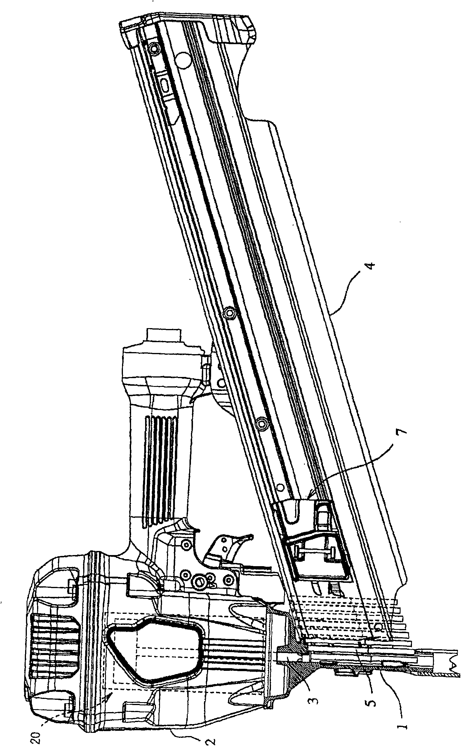
[0031] exist figure 1 Among them, the symbol 1 represents the head of the nailing machine. The machine head 1 is a tubular part extending below the nailing machine main body 2, which guides the sliding of the driving device 3 driven by the striking mechanism 20 arranged on the nailing machine main body 2, and to the nail box 4. The front end is opened to accommodate the head nails of the connecting nails 5 loaded in the nail case 4, and guide the head nails struck by the driver 3 to the driving direction.

[0032] The connecting nail 5 is formed by connecting a plurality of iron nails straightly in a rod shape through a connecting piece, and the heads of each nail are connected in a stacked state. The connector is made of materials such as synthetic resin and paper. The connecting nails 5 loaded in the nail magazine 4 are in a slightly inclined state with res...


PUM


Abstract

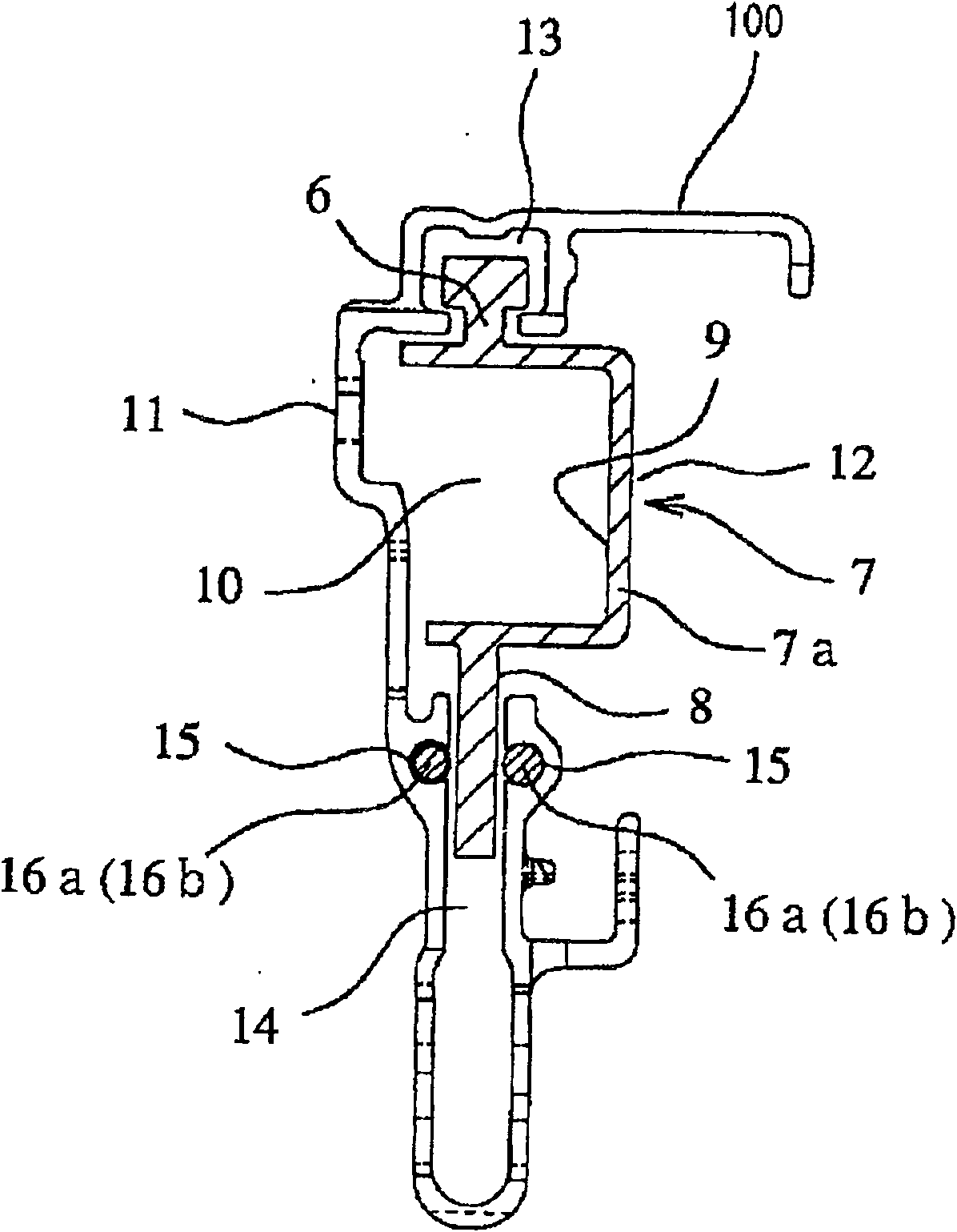
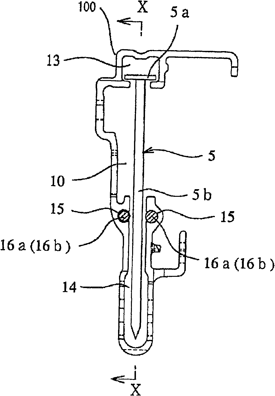
Along the full length of the nail box (4), a long groove (14) is formed for guiding the nail shaft portion of the connecting nail (5) and the lower part of the plate-shaped pushing portion of the pusher (7). A holding groove (15) opening into the long groove (14) is formed on the inner surface of the long groove (14). The first rod-shaped guide member is fitted and fixed from the head side to the middle portion of the holding groove, and the second rod-shaped guide member is fitted and fixed in the remaining part of the holding groove. The wear resistance of the first rod-shaped guide member is higher than that of the second rod-shaped guide member.

Description

technical field [0001] The present invention relates to a nail magazine of a nailing machine, in particular to a guide structure for guiding the connecting nails in the guide passage and pushing the connecting nails to the side of the machine head. Background technique [0002] Generally speaking, the nail magazine of a nailing machine is a part that pushes and supplies the connecting nails loaded inside by a pusher to the side of the machine head. Therefore, a guide path for guiding the sliding of the connecting nail and the pusher that pushes the connecting nail toward the head side of the nailing machine is formed in the nail magazine. Since the guide passage is a shared guide mechanism of the connecting nail and the pusher, the connecting nail and the pusher rub against the inner wall surface of the guide passage to move when sliding. [0003] Moreover, the main body of the nail magazine is usually made of aluminum or an aluminum alloy, which has low wear resistance and...

Claims


Application Information

Patent Timeline
Patent Type & Authority Patents(China)
IPC IPC(8): B25C1/00
CPCB25C1/005
Inventor 山本博纪
Owner MAX CO LTD
Learn More