Ink cartridge for ink jet recording device

A technology of ink cartridges and recording heads, which is applied in printing and other directions, can solve the problems of impossible printing, increase of remaining ink volume, and lower printing quality, and achieve the effect of easy ink storage and easy change

Inactive Publication Date: 2009-10-14
SEIKO EPSON CORP
View PDF9 Cites 2 Cited by
  • Summary
  • Abstract
  • Description
  • Claims
  • Application Information

AI Technical Summary

Problems solved by technology

Therefore, when the amount of remaining ink is small, the printing quality will be lowered, that is, the head pressure of the ink will be lowered below a predetermined level.
On the other hand, if printing quality must be ensured, the amount of remaining ink must be increased
[0010] In addition, if the printing quality is neglected in order to reduce the amount of waste ink for continuous printing, excessive negative pressure is required to open the membrane valve acting on the recording head, thereby destroying the meniscus of the nozzle on the recording head, making printing impossible. may have been carried out

Method used


Image

  • Ink cartridge for ink jet recording device
  • Ink cartridge for ink jet recording device
  • Ink cartridge for ink jet recording device

Examples


no. 1 example

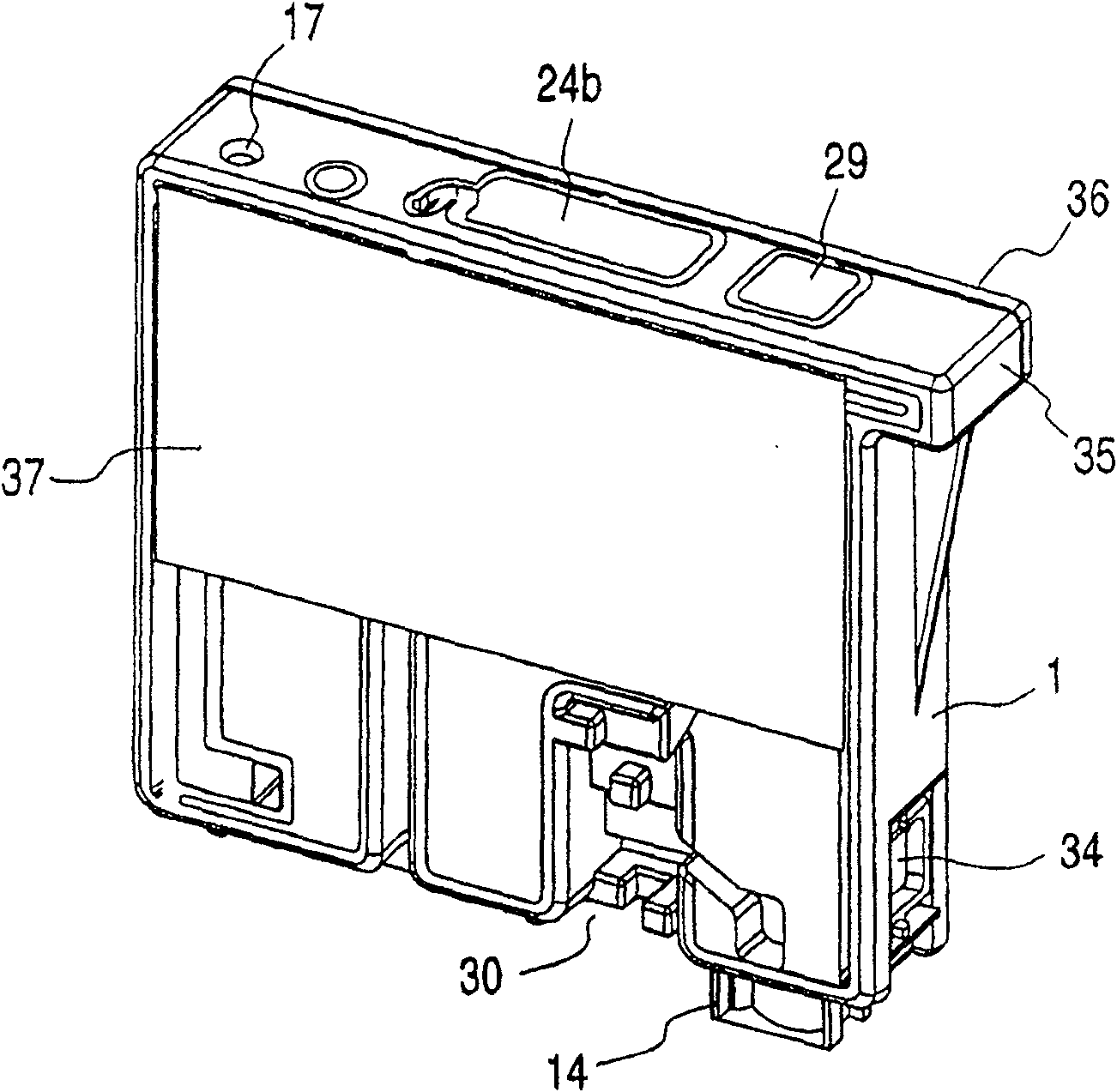
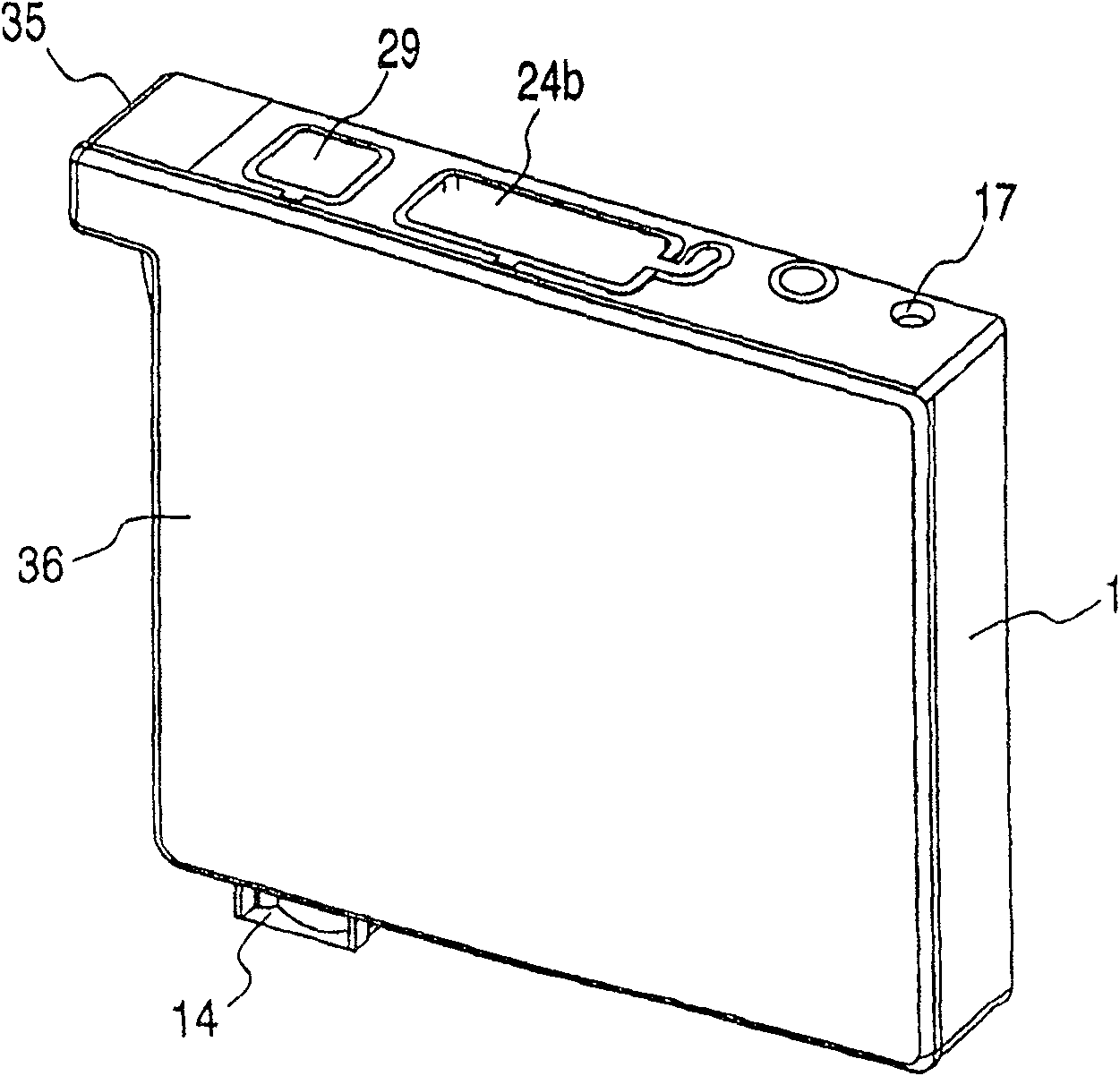
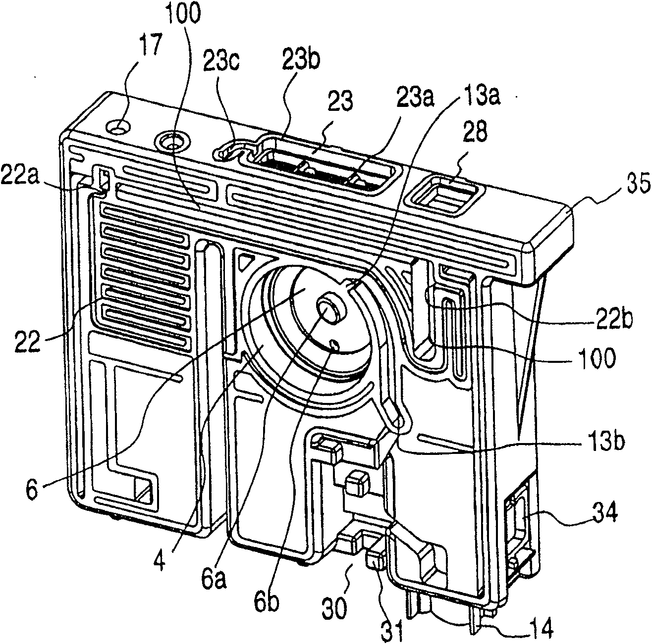
[0073] Figure 1A , 1B , 2A and 2B show the front and rear structures of the container main body 1 forming an ink cartridge, which constitutes the first embodiment of the present invention. image 3 Shown is the bottom structure of the container body 1 . The interior of the container body 1 is vertically divided into a lower region and an upper region by a substantially horizontally extending wall 2 . In the lower area, the first ink chamber 3 serving as the lower ink chamber is formed in the lower area. In the upper area, a differential pressure valve storage chamber 4 is formed as a negative pressure generating mechanism to be described below; a filter chamber 5 for storing a filter; and a second ink chamber 8 as an upper ink chamber, And also includes first and second ink storage portions 15 and 16 .

[0074] The differential pressure valve storage chamber 4 and the filter chamber 5 are separated from each other by a wall 6 located substantially at the central portion in...

no. 2 example

[0100] Figure 12A and 12B Shown is a schematic external view of an ink cartridge constituting a second embodiment of the present invention. The ink cartridge 61 is mainly composed of a flat, rectangular container main body 62 with its side open, and a cap member 63 for hermetically closing the opening. The container body 62 is integrally formed with the ink supply port at the front end of the ink cartridge, locking members 65 and 66 at the upper corners as viewed from the cartridge insertion direction (lower part in this embodiment). A storage device 67 is arranged below the locking element 65 . A valve reservoir 68 is arranged below the other locking element 66 . A valve member (not shown) is stored in the ink supply port 64 so that when the ink supply needle is inserted into the ink supply port 64, the valve member is opened.

[0101] Figure 13 and 14 Shown is a schematic view of the flow passage formed in the container body 62 of the ink cartridge. The inner space ...

no. 3 example

[0150] Figure 22A , 22B and 23A to 23D are schematic external views of another ink cartridge according to an embodiment of the present invention, which constitutes a third embodiment. The ink cartridge 61 is mainly composed of a flat, rectangular, box-shaped container main body 162, one surface of which is open and the other opposite surface is closed, and a cover member 163 for closing the open face of the container main body 162 is constituted. An ink supply port 164 is formed at a longitudinally offset position on the leading end side in the insertion direction, that is, on the bottom surface of this embodiment. Locking elements 165 and 166 are integrally formed with container body 162 at an upper lateral portion.

[0151] The locking element 165 near the ink supply port has a pivot point 165a which is slightly above the leading end side of the locking element 165 as viewed from the insertion direction, i.e. at the lower end of the locking element 165 of this embodiment....


PUM


Abstract

The present invention provides an ink cartridge for an ink jet recording device with a recording head, comprising: a container including: a lower ink chamber; an upper ink chamber; and an ink supply port for supplying ink to the recording head ; one ink suction channel that communicates the lower ink chamber with the upper ink chamber, and the lower ink chamber is located upstream of the upper ink chamber in relation to the direction in which the ink flows through the ink suction channel; one communicates the upper The ink chamber and the ink flow channel of the ink supply port; an air exchange part communicating with the lower ink chamber and the atmosphere; a negative pressure generating mechanism provided in the container and arranged in the ink flow channel.

Description

[0001] This application is a divisional application of an invention patent application with a filing date of October 20, 2001, an application number of 200410068528.9, and an invention title of "ink cartridge for an inkjet recording device". technical field [0002] The present invention relates to an ink cartridge for supplying ink at a suitable negative pressure to a recording head which ejects ink droplets in response to a printing signal applied thereto. Background technique [0003] An inkjet recording apparatus is generally constructed such that an inkjet recording head for ejecting ink droplets in response to a printing signal is mounted on a carriage that reciprocates in the width direction of a recording paper and is moved from Ink is supplied to the recording head from the ink tank. In such a compact recording apparatus, an ink storage container, such as an ink tank, is detachably attached to the carriage to ensure easy handling. [0004] Typically, the ink storag...

Claims


Application Information

Patent Timeline
Patent Type & Authority Patents(China)
IPC IPC(8): B41J2/175
Inventor 宫泽久坂井康人品田聪小林淳
Owner SEIKO EPSON CORP
Why Eureka
Try Eureka