Positive displacement pumping system

a pumping system and positive displacement technology, applied in the direction of piston pumps, pump control, borehole/well accessories, etc., can solve the problems of increasing operation and maintenance costs, rapid wear or even catastrophic failure of centrifugal pumps, and achieve the effect of reducing the head pressur

Inactive Publication Date: 2013-11-26
LACK LARRY
View PDF20 Cites 0 Cited by
  • Summary
  • Abstract
  • Description
  • Claims
  • Application Information

AI Technical Summary

Benefits of technology

[0009]The present invention is a positive displacement pumping system for use in deep wells. The pumping system includes a drive system and one or two pumps. In the preferred embodiment, the drive system includes an electrical motor, a speed reducer, and a rotary-to-reciprocal motion converter. In alternative embodiments, the drive system includes a windmill and a variable transmission. Where one pump is used with a windmill, a counterbalance can be included in the drive system. Preferably, however, two pumps are used side-by-side eliminating the need for a counterbalance and effectively reducing head pressure.

Problems solved by technology

Currently available systems, however, suffer from one or more drawbacks that increase operation and maintenance costs.
Centrifugal pumps have several drawbacks, however.
As a result, even small grains of sand or other contaminants can cause rapid wear or even catastrophic failure.
Another drawback of centrifugal pumps is that they must continuously maintain a certain minimum rpm before they will pump any liquid at all.
A further drawback of centrifugal pumps is that their speed cannot be controlled as needed.
Maintaining centrifugal pump systems can also be time consuming and expensive.
Additionally, periodic overhauls of the internal combustion engine cost approximately $3000.
Positive displacement pumps have not been traditionally used for deep-water well applications because deep wells require too large of a pump.
Another drawback to positive displacement pumps for use in deep underground aquifers is that a long vertical cylinder must be used.
While in shallower applications, the momentum of the fluid is sufficient to carry it out of the well bore, in deeper applications, the momentum may be insufficient.
Consequently, the fluid will not be pumped out of the well bore because the piston cannot lift the weight of the fluid in the cylinder and that above it.

Method used


Image

  • Positive displacement pumping system
  • Positive displacement pumping system
  • Positive displacement pumping system

Examples


Embodiment Construction

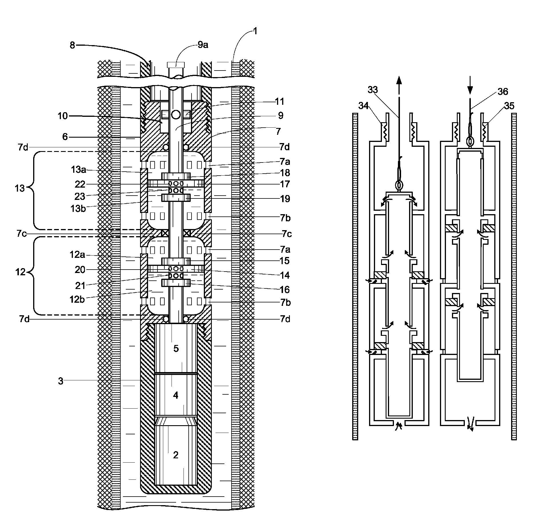
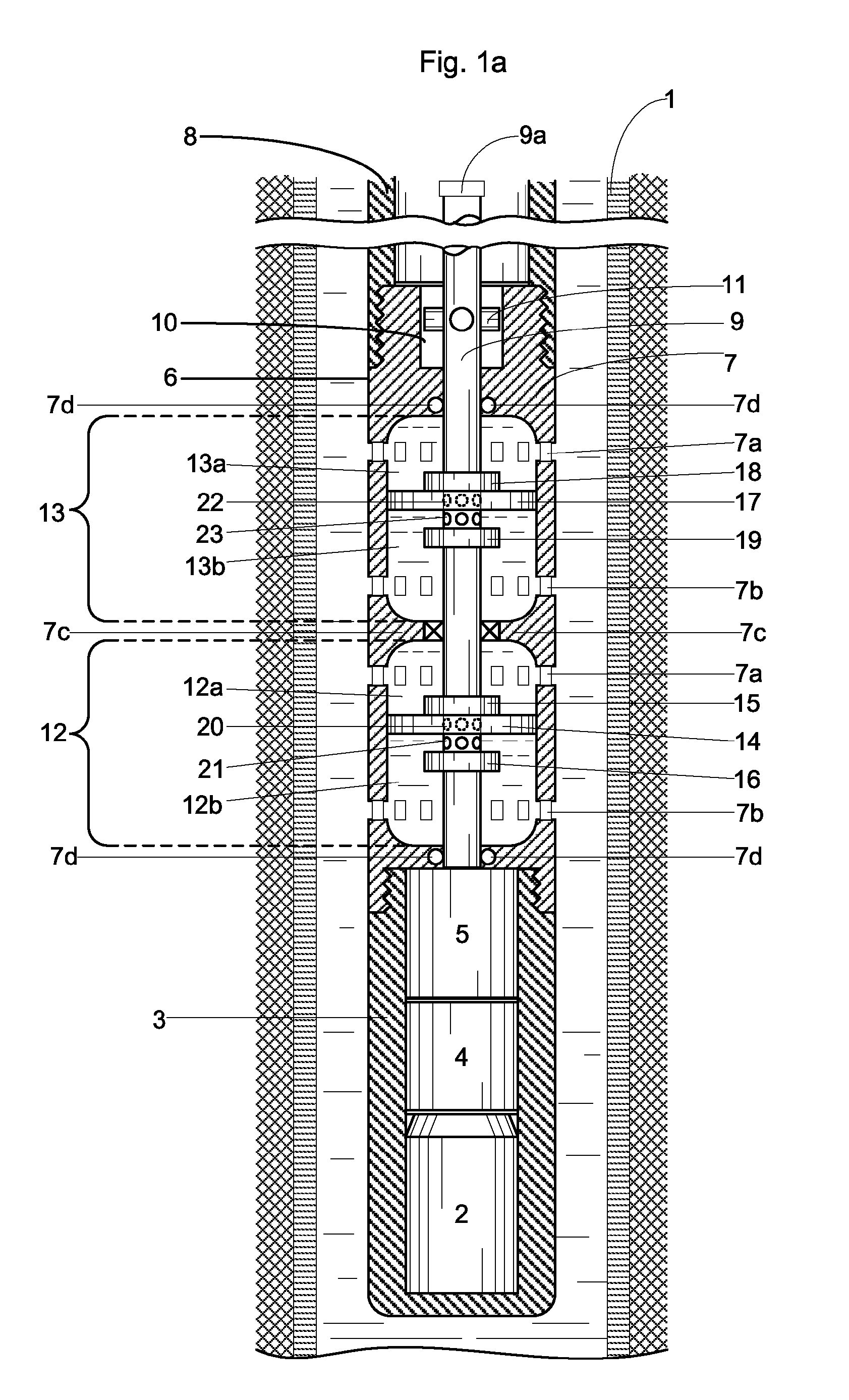
[0030]FIG. 1a illustrates the preferred embodiment of the present invention, a positive displacement pumping system for pumping fluids such as water or oil from deep wells. FIG. 1a shows the pumping system submersed in a deep well bore having a casing or wall 1. In general, the pumping system comprises a drive system that causes one or more pumps to reciprocate. In the preferred embodiment, the drive system comprises a motor 2, a speed reducer 4, and a rotary-to-reciprocal motion converter 5. Motion converter 5 connects to pump 6. Motor 2 is situated in a waterproof housing 3 and produces a rotary output directed to an input (not shown) of speed reducer 4. Speed reducer 4, which will be discussed in detail with reference to FIGS. 6a-6c, comprises several stages of planetary reduction gears. Preferably, the nominal speed of motor 2 is 1800 rpm and speed reducer 4 is configured to effect a thirty-to-one reduction for an output of 60 rpm. The output of speed reducer 4 is applied to the...


PUM


Abstract

A positive displacement pumping system for use in deep wells includes a drive system and one or two pumps. The drive system may include an electrical motor or a windmill. The pump include a central hollow discharge tube and one or more vertically aligned pumping chambers in fluid communication with the central discharge tube. Within each pumping chamber, a valve arrangement, which includes a piston or shuttle member and fluid intakes, causes fluid to fill and then drain from the pumping chambers as the central hollow discharge tube reciprocates. In operation, the drive system causes the central hollow discharge tube in the pump to reciprocate and thereby cause the fluid to travel from each pumping chamber into to the central discharge tube. In the preferred embodiment, fluid is pumped on both the upstroke and downstroke of the central discharge tube.

Description

FIELD OF INVENTION[0001]This invention relates to pumping systems and methods of pumping fluids such as water and oil. More particularly, this invention relates to a positive displacement pumping system for deep-water wells.BACKGROUND[0002]In many agricultural regions, deep-water wells are heavily relied upon to provide the water necessary to irrigate crops. In large-scale operations, these deep-water wells, which may be 1200-1300 feet deep, supply large volumes of ground water to the surface through deep well pumping systems. Currently available systems, however, suffer from one or more drawbacks that increase operation and maintenance costs.[0003]Traditionally, for large-scale deep-water wells, centrifugal pumps have been installed. A centrifugal pump is a rotodynamic pump that uses a rotating impeller to increase the velocity of a fluid. Generally, one or more cascaded multi-stage impeller pumps, or “bowls” as the stages are commonly called, have been used for approximately every...

Claims


Application Information

Patent Timeline
Patent Type & Authority Patents(United States)
IPC IPC(8): F04B35/04F04B17/04
CPCE21B43/126E21B43/128F04B3/003F04B17/02F04B47/02
Inventor LACK, LARRYLACK, PATRICIA
Owner LACK LARRY
Why Eureka
Try Eureka