
Plane structure of LED illuminating device

A technology of light-emitting diodes and planar structures, which is applied to semiconductor devices of light-emitting elements, identification devices, lighting devices, etc., can solve the problems of limiting LED application products, and achieve the effect of increasing configuration diversification and three-dimensionality.

Inactive Publication Date: 2009-10-14
POLYTRON TECH
View PDF5 Cites 5 Cited by
  • Summary
  • Abstract
  • Description
  • Claims
  • Application Information

AI Technical Summary

Problems solved by technology

However, in most known LED applications, LEDs are fixed or installed on a rigid and non-transparent carrier after the wiring of the LED is arranged. Such installation or fixing methods limit the size, size, shape and perspective of LED application products.

Method used


Image

  • Plane structure of LED illuminating device
  • Plane structure of LED illuminating device
  • Plane structure of LED illuminating device

Examples


Embodiment Construction

[0093] The following is a preferred embodiment to illustrate the planar structure of the LED lighting device of the present invention.

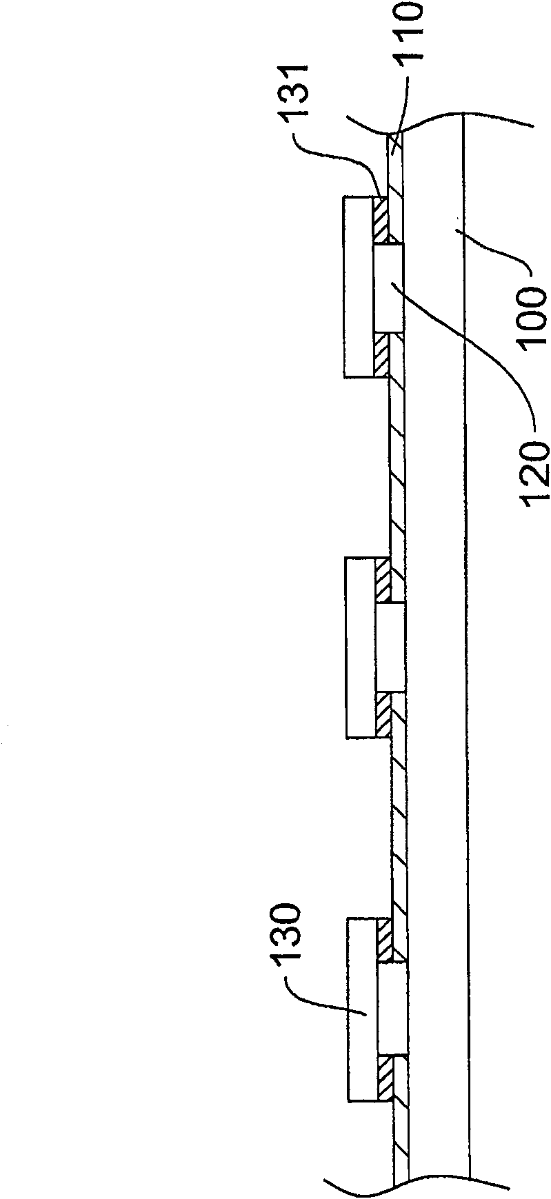
[0094] see Figure 1A , is a schematic cross-sectional view of the planar structure of the light-emitting diode light-emitting device according to the first embodiment of the present invention. As shown in the figure, the light-emitting diode light-emitting device includes: a transparent flexible roll-up tape 100, a first transparent pattern and a second transparent pattern 120 are arranged on the transparent flexible roll-up tape 100, and the first light-emitting diode 130 uses an adhesive The structure 131 is disposed on the first transparent pattern. In one embodiment, the transparent flexible tape 100 is made of insulating and flexible materials, such as polyethylene terephthalate (Poly (ethylene terephthalate), PET), polycarbonate (PC), Oriented polypropylene (OPP), polyvinyl chloride (PVC), thermoplastic polyurethane (TPU), polyethylen...


PUM


Abstract

The invention discloses a planar structure for a light emitting device of a LED, wherein, a transparent flexible tape is provided with a first transparent pattern and a second transparent pattern which are electrically insulated from each other; a plurality of LEDs are connected electrically with the first transparent pattern. A multi-layer flexible panel can be obtained with two sides of the transparent flexible tape or by printing the first transparent pattern and the second transparent pattern successively on the two sides of the transparent flexible tape. Thus, the planar structure which can be used for various display decoration and illumination is formed.

Description

technical field [0001] The invention relates to a planar structure of a light-emitting device, in particular to a planar structure of a light-emitting diode light-emitting device. Background technique [0002] With the advancement and development of technology, light emitting diodes (Light Emitting Diode, LED) play a pivotal role in many applications. Good, no discharge gas, and flat packaging, so it is widely used in lighting applications, landscape design, traffic signs, and electronic display tools. [0003] For example, in the application of commercial buildings and landscaping, LED lighting system can show the effect of light color change, not only can have good lighting function, but also have certain energy saving and colorful, dazzling decorative effect. However, in most known LED applications, LEDs are fixed or installed on a hard and non-transparent carrier after the wiring of the LED is arranged. Such installation or fixing methods limit the size, size, shape and...

Claims


Application Information

Patent Timeline
Patent Type & Authority Patents(China)
IPC IPC(8): H01L25/00H01L25/075H01L23/498F21S4/00G09F9/30F21S4/24F21Y115/10
Inventor 游荣贤郑大荣
Owner POLYTRON TECH
Learn More