Fastening tubular scaffold falsework

A technology of scaffolding and steel pipes, which is applied in the field preparation of formwork/formwork/work frames, building components, construction, etc., which can solve the critical load limit of steel pipe scaffolding formwork supports without fasteners, and the erection structure size without series, Material waste cost and other issues

Active Publication Date: 2009-10-28
ZHEJIANG CONSTR ENG GRP CO LTD
View PDF3 Cites 0 Cited by
  • Summary
  • Abstract
  • Description
  • Claims
  • Application Information

AI Technical Summary

Problems solved by technology

[0002] At present, the fastener-type steel pipe scaffold formwork supports used in construction sites do not have a series of erection structure dimensions, no accurate design regulations, no restrictions on the critical load of the fastener-type steel pipe scaffold formwork supports, and no one-to-one correspondence between the series of formwork support erection structures. critical load requirements
On-site erection based on experience, on the one hand, causes material waste and increases cost, on the other hand, causes safety hazards, and some even cause major safety accidents

Method used


Image

  • Fastening tubular scaffold falsework
  • Fastening tubular scaffold falsework
  • Fastening tubular scaffold falsework

Examples


Embodiment Construction

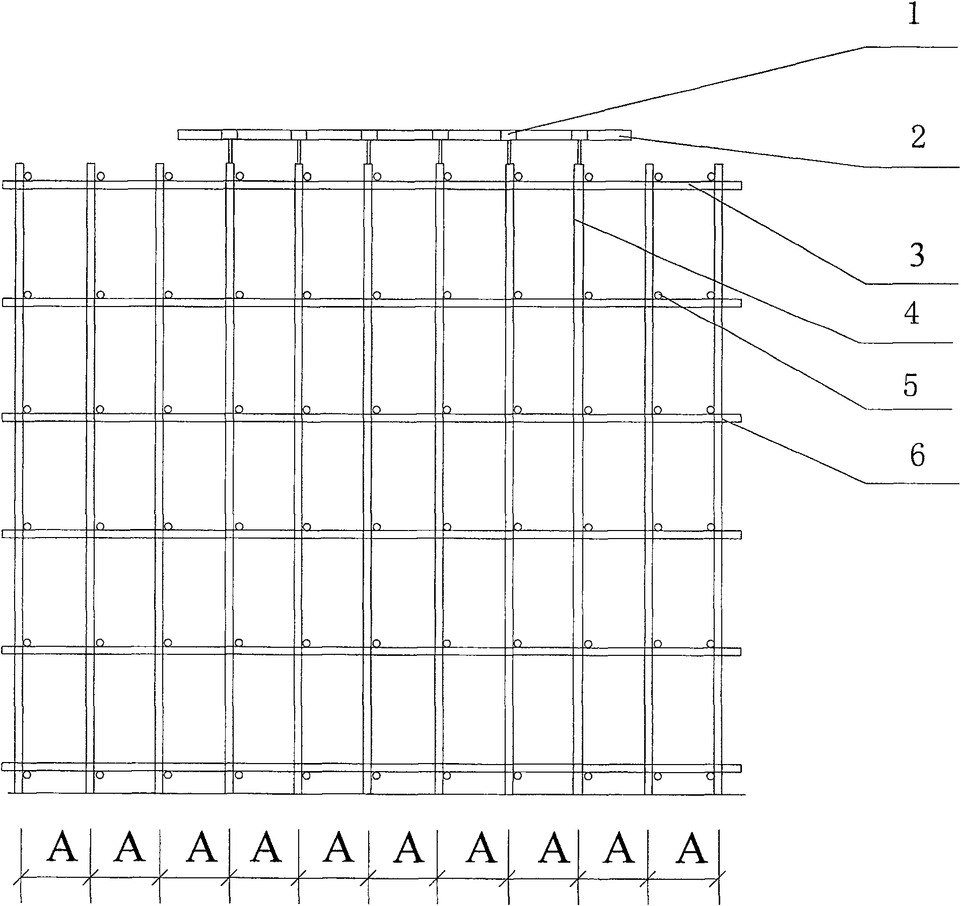
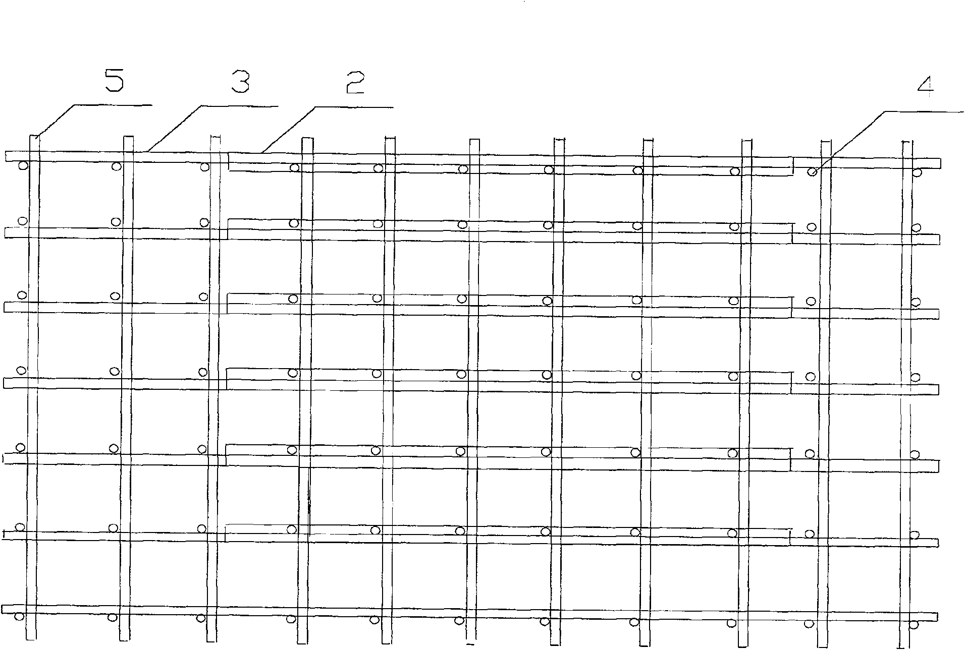
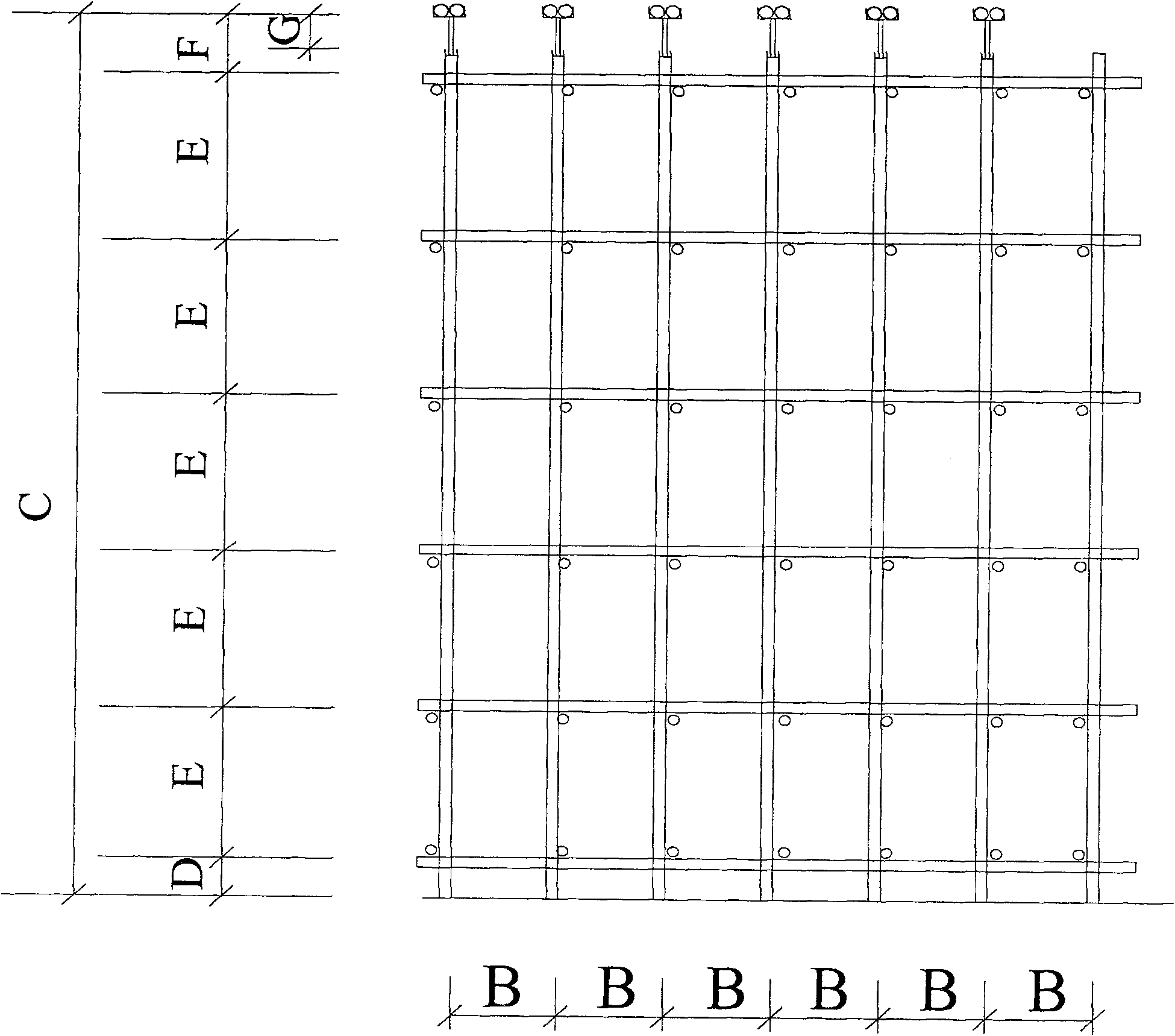
[0016] A fastener-type steel pipe scaffolding formwork support, including vertical steel pipes 4, longitudinal horizontal rods 3 and horizontal horizontal rods 5; the nodes are connected by malleable cast iron fasteners 6, and the upper part of the support is supported by an adjustable bracket 1 with Φ48×3.5 double steel pipes 2 As the main beam of the supporting template, the bottom of the adjustable bracket 1 is inserted into the support pole steel pipe 4 to be fixed. The stent has 10 spans in the longitudinal direction and 6 spans in the transverse direction. It is loaded in a range of 5 spans×5 spans, with 2 spans on one side of the longitudinal direction outside the loading area and 3 spans on the other side; The height-to-width ratio of the support = 8.15÷(6×0.94)=1.44; the height-to-width ratio of the support loading area=8.15÷(5×0.94)=1.73; the sweeping rod is the lower crossbar of the support, and D is the height of the sweeping rod.

[0017] The distance from the upper s...


PUM


Abstract

The invention relates to a fastener type formwork bracket for a steel pipe scaffold. The bracket is 10 spans in the longitudinal direction and 6 spans in the transverse direction, and is loaded in the range of 5 spans x 5 spans; the loaded region is 2 spans outside one side in the longitudinal direction, while 3 spans outside the other side; the loaded region is 1 span outside one side in the transverse direction, while the other side is not spanned; and the ratio of the height to the width of the bracket is 1.44. The height of the bracket is 8.15 meters, the step pitch of upright rods is 1.49 meters, the longitudinal pitch of the upright rods is 0.9 meter, the transverse pitch of the upright rods is 0.94 meter, the bracket is built by using phi 48 x 3.5 steel pipes, and joints of the steel pipes are connected by fastening pieces. The upper part of the bracket is provided with phi 48 x 3.5 dual steel pipes which are supported by an adjustable supporting base and are used as main girders for supporting the formwork, the upright rods of the bracket are inserted into the bottom of the adjustable supporting base to fix the adjustable supporting base, the upper surface of the adjustable supporting base is adjusted to 0.5 meter on the upper layer of a topmost transverse pipe of the bracket, and the upright rods extend 0.3 meter out from the adjustable supporting base and are adjusted within the range of 0.3 meter. The fastener type formwork bracket for the steel pipe scaffold has a safe and steady structure and is convenient to build and dismantle.

Description

Technical field [0001] The invention relates to a formwork support for construction sites, in particular to a fastener type steel pipe scaffold formwork support. Background technique [0002] The fastener-type steel tube scaffolding formwork bracket currently used in construction sites does not have a series of erection structure dimensions, no accurate design regulations, no limit on the critical load of the fastener-type steel tube scaffolding formwork bracket, and no series of formwork bracket erection structures that correspond to one-to-one Critical load requirements. The site is built based on experience. On the one hand, it causes increased material waste and cost, on the other hand, it causes safety hazards, and some even major safety accidents. Summary of the invention [0003] The purpose of the present invention is to provide a fastener-type steel tube scaffolding formwork support with reasonable structural dimensions, and to give the corresponding critical load, so t...

Claims


Application Information

Patent Timeline
Patent Type & Authority Patents(China)
IPC IPC(8): E04G11/48E04G11/50
Inventor 吴飞金睿刘群
Owner ZHEJIANG CONSTR ENG GRP CO LTD
Why Eureka
Try Eureka