Supercharge Your Innovation With Domain-Expert AI Agents!

Retainer positioning structure for linear sliding rail

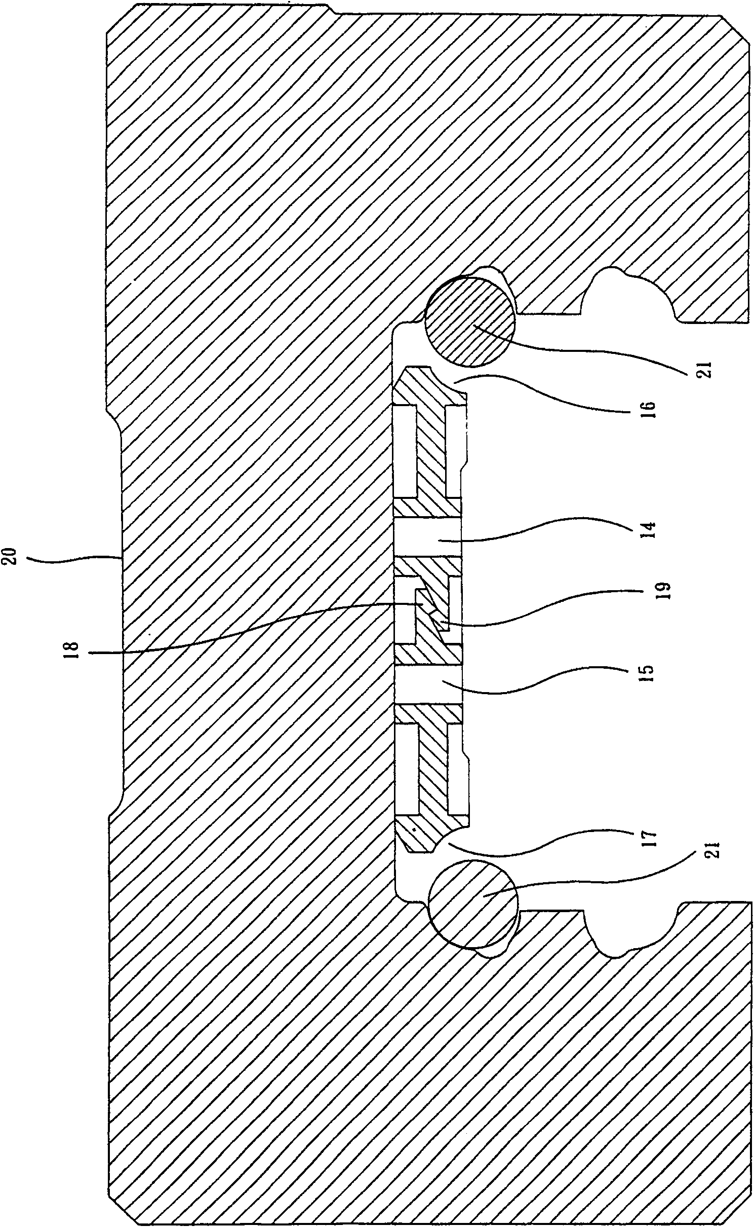
A linear slide rail and positioning structure technology, applied in the direction of linear motion bearings, bearings, shafts and bearings, etc., can solve the problems of easy deformation, difficult shrinkage and deformation of the retainer, and inability to play the guiding ball 21, etc., so as to achieve easy assembly and disassembly , the effect of easy replacement

Inactive Publication Date: 2009-11-04
HIWIN TECH
View PDF8 Cites 0 Cited by
  • Summary
  • Abstract
  • Description
  • Claims
  • Application Information

AI Technical Summary

Problems solved by technology

However, this conventional retainer 10 is beneficial to be shrinkable and deformable, and it must select a material that is relatively easy to deform, so that the two guide portions 16, 17 are also easily deformed, so that the function of guiding the ball 21 cannot be brought into play. Choose a material that is not easily deformed, and it is not easy to shrink and deform the middle position of the long and wide sides of the retainer 10

Method used


Image

  • Retainer positioning structure for linear sliding rail
  • Retainer positioning structure for linear sliding rail
  • Retainer positioning structure for linear sliding rail

Examples


Embodiment Construction

[0041] In order to make your examiners and people who are accustomed to this technology have a further understanding of the present invention, a preferred embodiment is given hereafter, and the details are as follows: (but, this embodiment is only for illustration, and the future development of the present invention Implementation is not limited to this, and all improvements and implementations based on the technical features of the present invention are bound by the present invention).

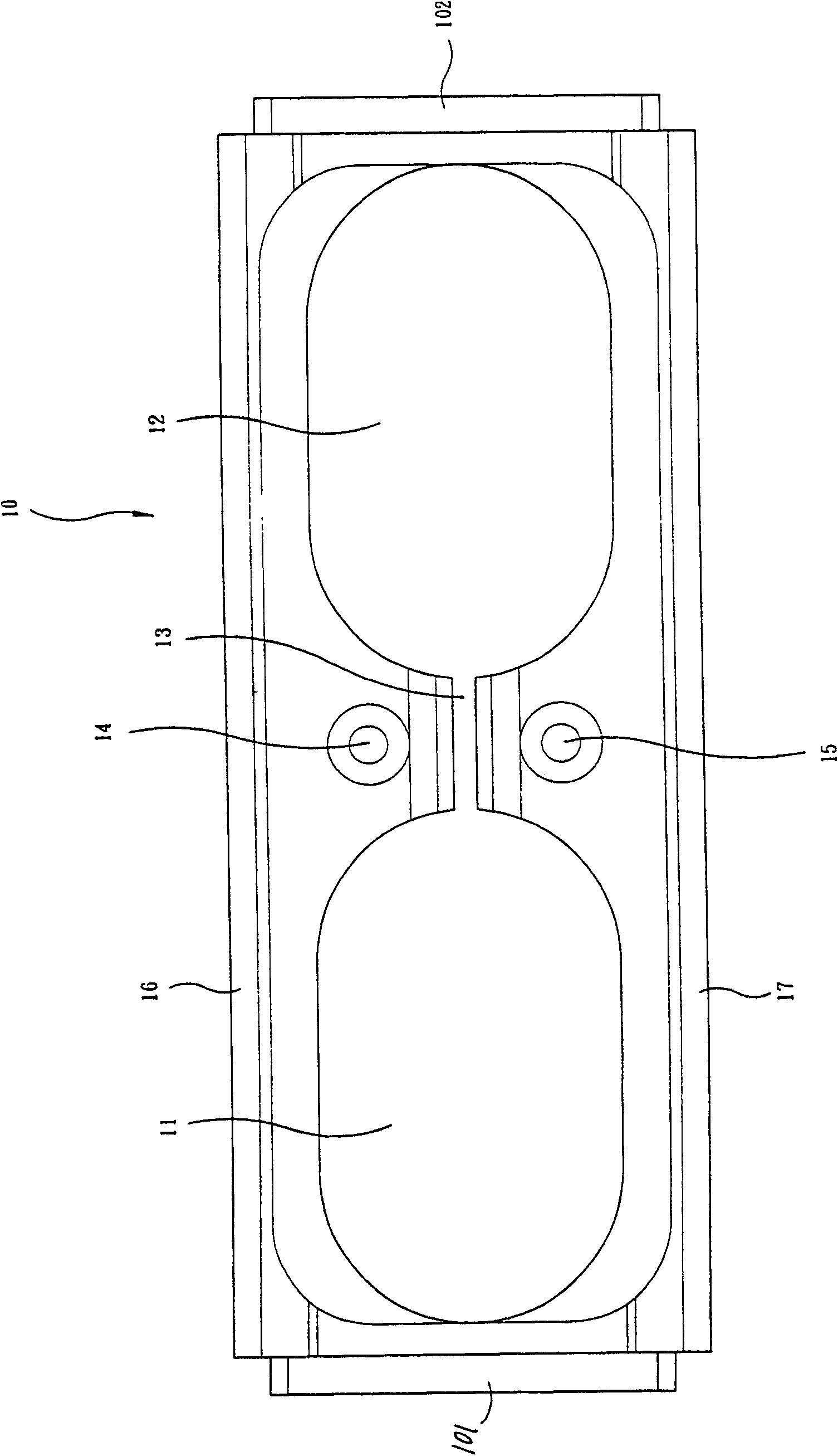
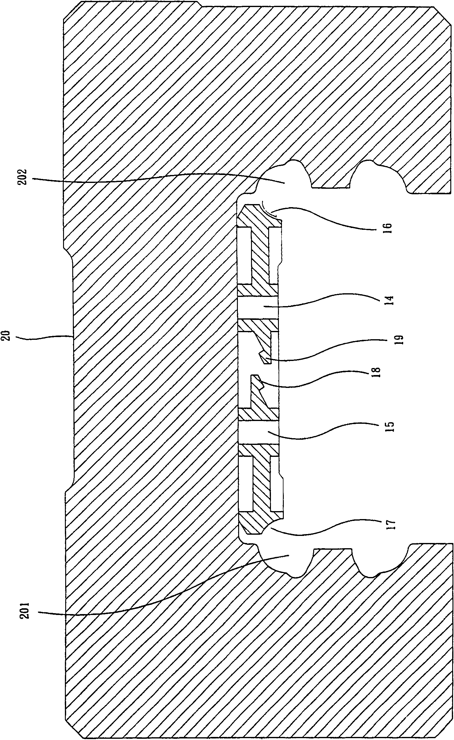
[0042] see Figure 3 to Figure 6 As shown, the retainer 40 of the present invention is inserted between the end caps 32, 34 at both ends of the slider 30, and a return element 33 is clamped between each end cap 32, 34 and the opposite side of the slider 30 (end cap 32 and The return element between the sliders 30 is not seen), and the other side of each end cover 32, 34 is provided with an oil scraper 31, 35. After the above-mentioned components are assembled, they are nested on the slide rai...


PUM


Abstract

The invention discloses a retainer positioning structure for a linear slide rail. The retainer is a long strip-shaped block, one long side of which is formed as an arc-shaped guide part, and two ends of which are respectively provided with a protruding bump. The bottom ends of the sides of each projection form a downwardly protruding block portion, and the two retainers are attached to the inner top surface of the slider of the linear slide rail, and the two ends of each retainer are inserted between the two end covers, and each The end cover is provided with an accommodating groove corresponding to the protrusion of each retainer, and each accommodating groove is formed with a locking groove corresponding to the block part of each protrusion for the corresponding block part to be embedded, so that the retainer can be installed on Between the two ends of the cover; the retainer can be easily assembled and disassembled due to the structural design that the locking part of the retainer and the retaining groove of the end cover are easy to engage with each other for positioning and release.

Description

technical field [0001] The invention relates to a linear slide rail, in particular to a retainer positioning structure of the linear slide rail. Background technique [0002] see figure 1 As shown, it is a rectangular sheet-shaped retainer 10, each side of which is provided with a through hollow part 11, 12, and a slender through slot 13 is communicated between the two hollow parts 11, 12, corresponding to the thin The other two sides of the slotted hole 13 are respectively provided with a perforation 14, 15, and the outside of the short and wide side of the protector 10 is respectively provided with a protruding strip 101, 102, and the two protruding strips 101, 102 can be fixed on both sides of the slider 20. The end cap (not shown) is clamped and fixed, and the sides of the long and wide sides of the retainer 10 are respectively formed into arc-shaped guides 16 and 17, please refer to Figure 2A , B, and C, the bottom between the elongated slot 13 and the two through ho...

Claims


Application Information

Patent Timeline
Patent Type & Authority Patents(China)
IPC IPC(8): F16C29/06
Inventor 陈锦盛
Owner HIWIN TECH
Features
  • R&D
  • Intellectual Property
  • Life Sciences
  • Materials
  • Tech Scout
  • Unparalleled Data Quality
  • Higher Quality Content
  • 60% Fewer Hallucinations
Learn More