Device and method for disengaging detecting safe coupling of roller mill main axle

A technology of safety coupling and detection device, which is applied to the driving device of metal rolling mill, safety equipment of roll, length measuring device, etc., which can solve the problems of increased grinding amount of work roll, scratches, and affecting enterprise benefits, etc.

Active Publication Date: 2009-11-18
BAOSHAN IRON & STEEL CO LTD
View PDF6 Cites 0 Cited by
  • Summary
  • Abstract
  • Description
  • Claims
  • Application Information

AI Technical Summary

Problems solved by technology

However, when the sum of these two forces is not enough to completely drive the disengaged roll, the work roll will move relative to the surface of the steel plate, resulting in slippage
The slipping is likely to cause scratches on the roll surface of the roll, resulting in an increase in the amount of grinding of the work roll, which directly affects the profitability of the enterprise

Method used


Image

  • Device and method for disengaging detecting safe coupling of roller mill main axle
  • Device and method for disengaging detecting safe coupling of roller mill main axle
  • Device and method for disengaging detecting safe coupling of roller mill main axle

Examples


Embodiment 1

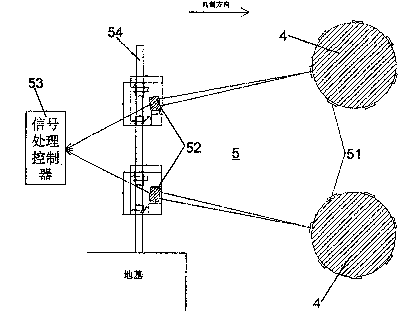
[0036] see image 3 As shown, the disengagement detection device 5 of the safety coupling of the main shaft of the rolling mill of the present invention includes a reflector 51, a photoelectric component 52 and a signal processing controller 53, and reflectors 51 of equal size and number are respectively arranged on the upper and lower sides of the rolling mill. On the surface of the safety coupling 4 of the roller, there are at least two reflectors 51 on the disengagement side surface of each safety coupling 4, and the number of reflectors 51 is selected by the installation position on the safety coupling 4 in addition. The limit and depends on the response speed of photoelectric components, the more the number, the faster the response time. In this embodiment, in order to avoid covering the screw holes on the safety coupling, a square polygonal reflector with a side length of 100 mm is selected as a reflector, and seven reflectors are evenly and equally divided around each s...

Embodiment 2

[0038]The steps of the method for detecting disengagement of the safety coupling of the main shaft of the rolling mill of the present invention are: during the operation of the rolling mill, use a photoelectric component to emit light to the disengagement side of the safety coupling; the photoelectric component selects two infrared beams of the same type The photoelectric components of the rolling mill are respectively arranged on the fence bars on the entrance side of the rolling mill about five meters away from the safety couplings of the upper and lower rolls of the rolling mill, and correspond to the safety couplings of the upper and lower rolls respectively. The fence bars are placed on On the foundation, most vibration factors can be eliminated. Then the reflected light of the reflective plate on the safety coupling is received by the photoelectric component, and a pulse signal is formed; the reflective plate is respectively set on the surface of the safety coupling of th...


PUM


Abstract

A disengagement detection device for a safety coupling of a main shaft of a rolling mill, including a reflector, which is arranged on the disengagement side surface of the safety coupling of the upper and lower rolls of the rolling mill, and the disengagement side surface of each safety coupling There are at least two reflectors; two photoelectric components are arranged on the entrance side of the rolling mill and correspond to the safety couplings of the upper and lower rolls respectively, and emit light to the safety couplings and receive the reflected light of the reflectors; signal processing The controller receives and processes the signal of the photoelectric component, and performs alarm and shutdown control. The method of the present invention includes: during the operation of the rolling mill, using two photoelectric components to emit light on the disengaged side of the safety coupling of the upper and lower rolls, and receiving the reflected light of the reflective plate arranged on the safety coupling; using a signal processing controller Process the signal of photoelectric components, timely alarm and shutdown control. The device and method can quickly detect the disengagement of the safety coupling, is simple, convenient, accurate and stable, easy to maintain, and has a certain fault tolerance.

Description

technical field [0001] The present invention relates to detection equipment and technology for protecting the main shaft of a rolling mill, more specifically, to a disengagement detection device and method for a safety coupling of a main shaft of a rolling mill. The safety coupling can be quickly detected by using the device and method disengaged. Background technique [0002] During steel rolling in a steel mill, see figure 1 As shown, the main shaft of the thick plate rolling mill includes upper and lower work rolls 1 and upper and lower cardan shafts 2, the work rolls 1 are respectively connected to one end of the cardan shaft 2, and the other ends of the cardan shaft 2 are respectively connected to the corresponding motor 3 , through the rotation of the motor 3, the work roll 1 is driven to rotate, so that the thick plate rolling mill works. A hydraulic safety coupling 4 is set between the cardan shaft 2 and the motor 2 to protect the main shaft of the rolling mill, se...

Claims


Application Information

Patent Timeline
Patent Type & Authority Patents(China)
IPC IPC(8): B21B38/00B21B33/00B21B35/14
Inventor 许武辉廖研仲鉴毛卫山顾华汪鎏
Owner BAOSHAN IRON & STEEL CO LTD
Why Eureka
Try Eureka