
Detaching and assembling tool for gate valve plate and seat

A valve plate and seat technology, which is applied in the field of gate valve plate and seat assembly and disassembly tools, can solve the problems that the valve seat cannot be disassembled and the operation is difficult

Active Publication Date: 2009-12-02
BC P INC CHINA NAT PETROLEUM CORP +1
View PDF4 Cites 0 Cited by
  • Summary
  • Abstract
  • Description
  • Claims
  • Application Information

AI Technical Summary

Problems solved by technology

[0002] In the prior art, scissor tools are used to assemble and disassemble the seat of the gate valve plate with wave spring. When installing and disassembling the seat of the gate valve plate, it is necessary to put the pull block at the front end of the tool into the seat Only in the groove can the valve seat be tightened, so as to install the valve plate. The disadvantage of the prior art is that the head of the pulling block is located at the front end of the scissor arm of the assembly and disassembly tool, and the center of rotation of the scissor arm is in the middle of the scissor arm. , so when the scissor arm is opened, the running trajectory of the pull block at the front end of the scissor arm will open according to a circular trajectory, so that the pull block at the front end of the scissor arm is not easy to be embedded in the groove of the valve seat, and it needs to be pulled repeatedly. Only the insertion of the block can make the puller enter the groove of the valve seat. Due to repeated friction, the head of the puller will become a circular arc due to wear and tear. The puller head of the arc makes the operation more difficult. When the puller After the head of the valve is worn out, the whole tool can only be scrapped; in addition, the scissor tool can only tighten the valve seat to assemble and disassemble the valve plate, but when the valve seat is stuck in the valve body hole, it cannot be used to disassemble the valve seat

Method used


Image

  • Detaching and assembling tool for gate valve plate and seat
  • Detaching and assembling tool for gate valve plate and seat

Examples


Embodiment Construction

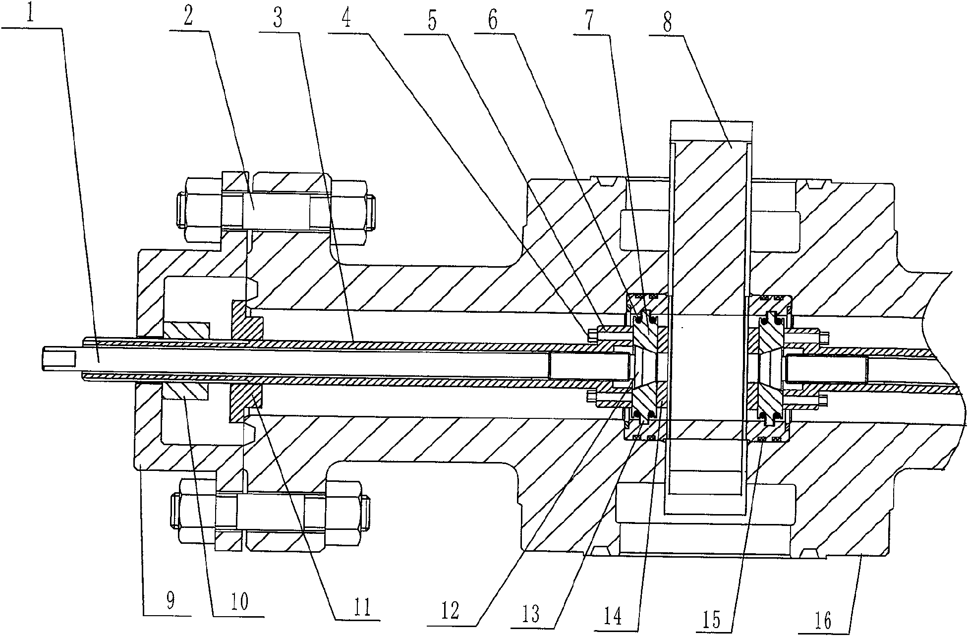
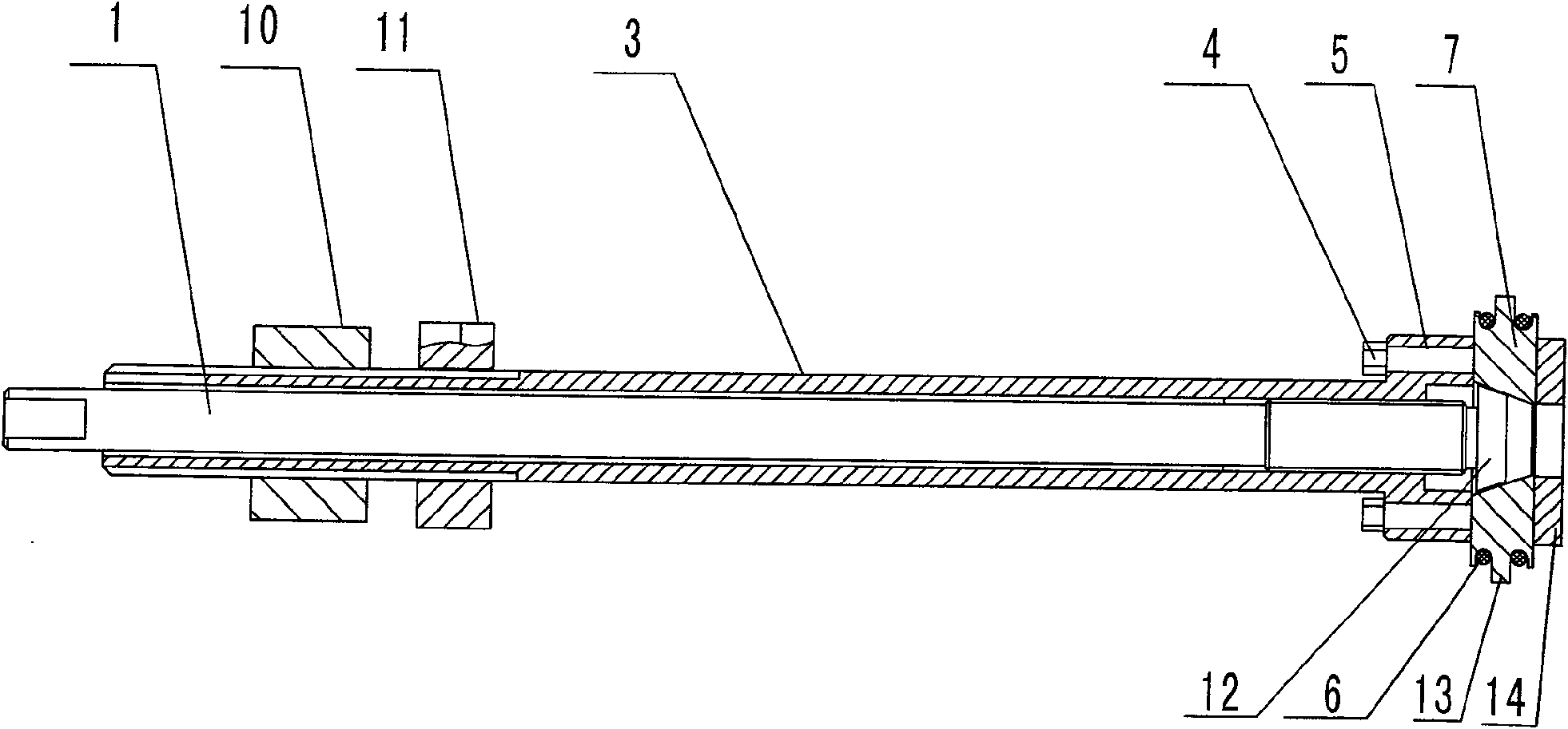
[0019] The present invention is achieved in that the present invention includes a push mechanism and an expansion mechanism, the push mechanism is composed of a push rod 1, a pull rod 3, a connecting bolt 4, a block 11, a nut 10, a pull rod seat 9 and a bolt 2, and the pull rod 3 It is hollow, and the push rod 1 is arranged in the pull rod 3, and the front end of the push rod 1 is provided with a conical body 12. The flange on the end face of the valve body is fixedly connected with the tie rod seat 9 by the bolt 2, the nut 10 and the stopper 11 are respectively turned on the tie rod 3 and sleeved on the tie rod 3;

[0020] The extrusion mechanism is composed of an expansion core block 7, an expansion core block seat 14, and an o-shaped rubber sealing ring 6. The expansion core block 7 is composed of two semicircles, or three semicircles; in the middle of the outer circle of the expansion core block 7 The expansion core block protrusion 13 is provided, and the expansion core b...


PUM


Abstract

A valve seat assembly and disassembly tool for a gate valve valve belongs to the technical field of gate valve maintenance tool manufacturing. It adopts the method of vertically inserting the pull block into the groove of the valve seat, and designs a tool that can not only assemble and disassemble the valve plate, but also be used for generating the valve seat. The gate valve valve plate valve seat installation and disassembly tool for dismantling the valve seat when it is jammed, including the push mechanism and the expansion mechanism. In the pull rod, the flange on the end face of the valve body is provided with a pull rod seat, a nut and a stopper by bolts; it solves the problem that the head of the pull block in the prior art is difficult to operate due to wear and cannot be used to disassemble the valve seat The problem is fast and durable. By lengthening and shortening the length of the tie rod and the ejector rod, it is suitable for the assembly and disassembly of the valve plate and the disassembly of the valve seat of the 65mm diameter gate valve of various pressure levels.

Description

Technical field: [0001] The utility model relates to a tool for installing and disassembling a valve plate and seat of a gate valve, which is used for assembling and disassembling a valve plate and seat of a gate valve of oil and gas wellhead devices and well control equipment, and belongs to the technical field of maintenance tool manufacturing for gate valves on well head devices and well control equipment. Background technique: [0002] In the prior art, scissor tools are used to assemble and disassemble the seat of the gate valve plate with wave spring. When installing and disassembling the seat of the gate valve plate, it is necessary to put the pull block at the front end of the tool into the seat Only in the groove can the valve seat be tightened, so as to install the valve plate. The disadvantage of the prior art is that the head of the pulling block is located at the front end of the scissor arm of the assembly and disassembly tool, and the center of rotation of the ...

Claims


Application Information

Patent Timeline
IPC IPC(8): B25B27/24E21B33/03
Inventor 杨学峰李萍陈文斌
Owner BC P INC CHINA NAT PETROLEUM CORP
Learn More