Cutting device

A cutting device and cutting edge technology, applied in maintenance and safety accessories, measuring/indicating equipment, electrical components, etc., can solve the problems of identifying cutting blades, not being able to detect cutting blade defects, wear, and optical fibers hindering movement, etc., to achieve contrast clear effect

Active Publication Date: 2009-12-09
DISCO CORP
View PDF7 Cites 3 Cited by
  • Summary
  • Abstract
  • Description
  • Claims
  • Application Information

AI Technical Summary

Problems solved by technology

Therefore, in a configuration in which light is irradiated to the cutting blade and the reflected light is captured, the cutting water is splashed by the high-speed rotation of the cutting blade, and the spray of the cutting water scatters the reflected light, and the cutting blade may not be recognized from the obtained image. , so sometimes it is impossible to detect the chipping, wear, etc. of the cutting insert
[0006] In addition, the light emitted from the light-emitting element is guided to the vicinity of the cutting blade by the optical fiber, and the reflected light is also guided to the light-receiving element by the optical fiber. Due to the poor flexibility of the optical fiber, there is also the problem of difficult wiring.
In addition, since the cutting unit including the cutting blade moves during cutting, the optical fiber also moves. In this way, there is also a problem that the optical fiber lacking in flexibility hinders the movement.

Method used


Image

  • Cutting device
  • Cutting device
  • Cutting device

Examples


Embodiment Construction

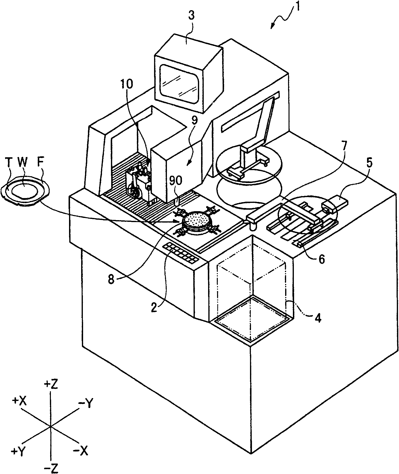
[0025] figure 1 The cutting device 1 shown is a device for cutting a workpiece to be divided into individual chips, and an operation unit 2 for an operator to input various information such as cutting conditions is provided on the front side. In addition, a display unit 3 capable of displaying various information including images is provided on the upper part of the device.

[0026] As an example of the workpiece to be cut, there are many devices formed on the surface. figure 1 Wafer W is shown. When cutting the wafer W, the wafer W is attached to the tape T, and the ring-shaped frame F is also attached to the tape T, so that the wafer W and the frame F are integrated through the tape T. In this way, a plurality of wafers W supported by the frame F via the tape T are accommodated in the wafer cassette 4 .

[0027] On the −Y direction side of the wafer cassette 4 is disposed a transport unit 5 that has functions of transporting uncut wafers W from the wafer cassette 4 and st...


PUM


Abstract

The light emitting unit (109) and the imaging unit (114) constituting the cutting insert detection unit (132) for detecting the state of the cutting edge of the cutting insert face each other and attached to the insert cover (104). Since the light-emitting unit (109) and the imaging unit (114) are opposite to each other, even if there is spray of cutting water, it is possible to clearly recognize the outer peripheral shape of the cutting edge portion (102a) of the cutting insert (102). image. In addition, by attaching the light emitting unit (109) and the imaging unit (114) to the blade cover (104), it is unnecessary to use an optical fiber and no wiring is required. In this way, in the cutting device having the function of taking an image of the cutting edge portion of the cutting insert and detecting its defect and wear, the state of the cutting insert can be reliably grasped without being constrained by the wiring of the optical fiber through which the light for imaging passes. Take a video.

Description

technical field [0001] The present invention relates to a cutting device having a cutting blade, and more particularly to a cutting device having a function of detecting the state of chipping and wear of the cutting blade. Background technique [0002] Wafers formed with multiple devices such as LCs and LSIs are cut vertically and horizontally by cutting blades rotating at high speeds, and are divided into individual chips for use in various electronic devices. [0003] The above-mentioned cutting insert is mounted on a high-speed rotating spindle and used, and a cutting edge portion is formed on the outer periphery thereof. The cutting edge portion is formed by fixing abrasive grains made of diamond or the like by means of electroforming, metal bonding, or resin bonding. Therefore, cutting causes the cutting edge portion to deteriorate over time, causing chipping and wear, and there are defects caused by cutting. The problem that the quality of each device deteriorates. ...

Claims


Application Information

Patent Timeline
Patent Type & Authority Patents(China)
IPC IPC(8): B23Q17/09B23Q17/24B23Q11/08B23Q11/10H01L21/304
Inventor 关家一马根岸克治米泽昭吉田圭吾
Owner DISCO CORP
Why Eureka
Try Eureka