Sensor device, method for position detection, and magnetic element for a sensor device

A sensor element and sensor device technology, applied in transmission control, elements with teeth, magnetic sensor arrays, etc., can solve problems such as inability to output gear selection, and achieve improved measurement accuracy, good distinguishability, and greater Hamming. effect of distance

Inactive Publication Date: 2014-08-13
ZF FRIEDRICHSHAFEN AG
View PDF7 Cites 6 Cited by
  • Summary
  • Abstract
  • Description
  • Claims
  • Application Information

AI Technical Summary

Problems solved by technology

However, since six codewords are required to output P, ​​R, N, D, +, -, the sensor set shown cannot output a select with a Hamming distance ≥ 3

Method used


Image

  • Sensor device, method for position detection, and magnetic element for a sensor device
  • Sensor device, method for position detection, and magnetic element for a sensor device
  • Sensor device, method for position detection, and magnetic element for a sensor device

Examples


Embodiment Construction

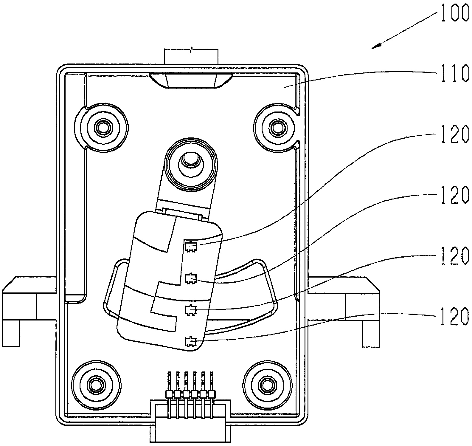
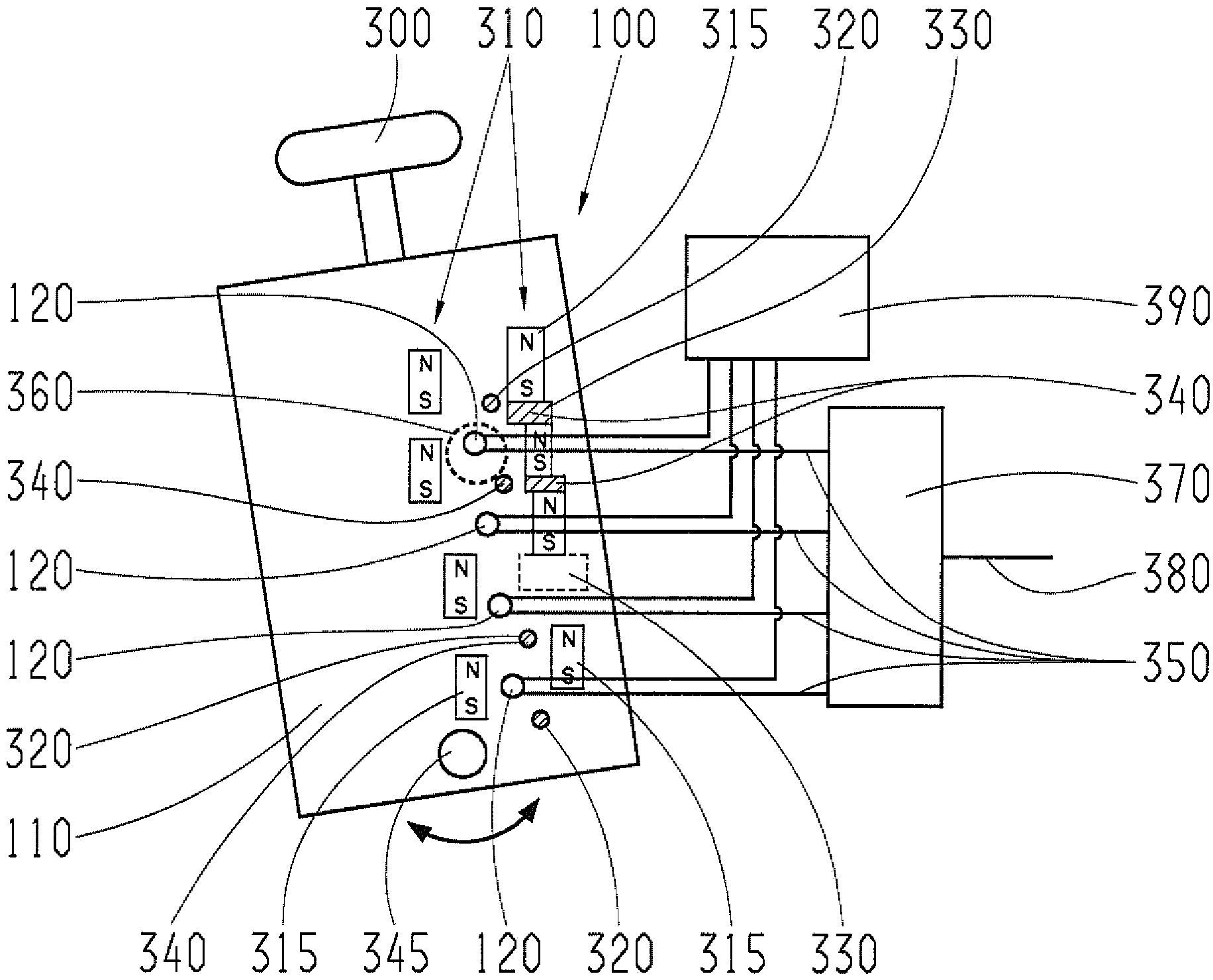
[0034] exist image 3 The middle figure shows a block diagram of an exemplary embodiment of the invention as sensor device 100 . The sensor device 100 is arranged, for example, on a selector lever 300 of an automatic transmission and comprises at least one magnetic element 110 on which differently magnetized regions 310 are present. These magnetically different regions can be formed, for example, by permanent magnets 315 which are embedded in the magnetic element 110 or glued to the magnetic element 110 . Furthermore, holes 320 and / or recesses 330 (ie cutouts in the plate-like carrier of magnetic element 110 ) can also be introduced in magnetic element 110 . Alternatively or additionally, diamagnetic elements 340 may be introduced in these holes 320 and / or recesses 330, so as to realize the concentration of the magnetic field to the area of ​​the magnetic element 110 that is not filled with diamagnetic elements 340, in addition, the sensor device 100 also includes At least o...


PUM


Abstract

The invention relates to a sensor device (100) having at least one sensor element (120), in particular a Hall sensor element, and at least one magnetic element (110) that is movable relative to the sensor element (120) and has a plurality of differently magnetizable regions (310). According to the invention, the sensor element (120) is designed to output a sensor signal (350) that represents a status in respect of a magnetization of a region of the magnetic element (110) located in the measurement region (360) of the sensor element (120) by one of at least three predefined sensor signal values.

Description

technical field [0001] The invention relates to a sensor device, a method for detecting the position of a magnetic element relative to a sensor element and a magnetic element for such a sensor device according to the main claim. Background technique [0002] Currently, in some applications for gear selector switches a magnetic plate is used, which is moved by the selector lever and its position is detected by Hall sensors, as in e.g. figure 1 The switching lever sensor system 100 is shown as an example in the figure. For evaluating the switching lever position, the switching lever sensor system has a magnetic plate 110, the magnetic area of ​​which is controlled by a plurality of sensors 120, especially designed as Hall sensors. read. Here, the Hall sensor 120 and the downstream evaluation logic recognize one direction of the magnetic field as a "1" and the other as a "0", so that each sensor can output two values (That is to say, work as a binary sensor), and these two va...

Claims


Application Information

Patent Timeline
Patent Type & Authority Applications(China)
IPC IPC(8): G01D5/14
CPCG01R33/072Y10T74/20018B62M25/00G01D5/145H01F7/021F16H59/02G01R33/0094B62K2207/00F16H59/105
Inventor 拉尔夫·普法伊费尔安德烈亚斯·波伊克特
Owner ZF FRIEDRICHSHAFEN AG
Why Eureka
Try Eureka