

Scanning type probe microscope and probe moving control method therefor
- Summary
- Abstract
- Description
- Claims
- Application Information
AI Technical Summary
Benefits of technology
Problems solved by technology
Method used
Image

Examples
Embodiment Construction
[0018] Below, preferred embodiments of the present invention will be explained with reference to the drawings.
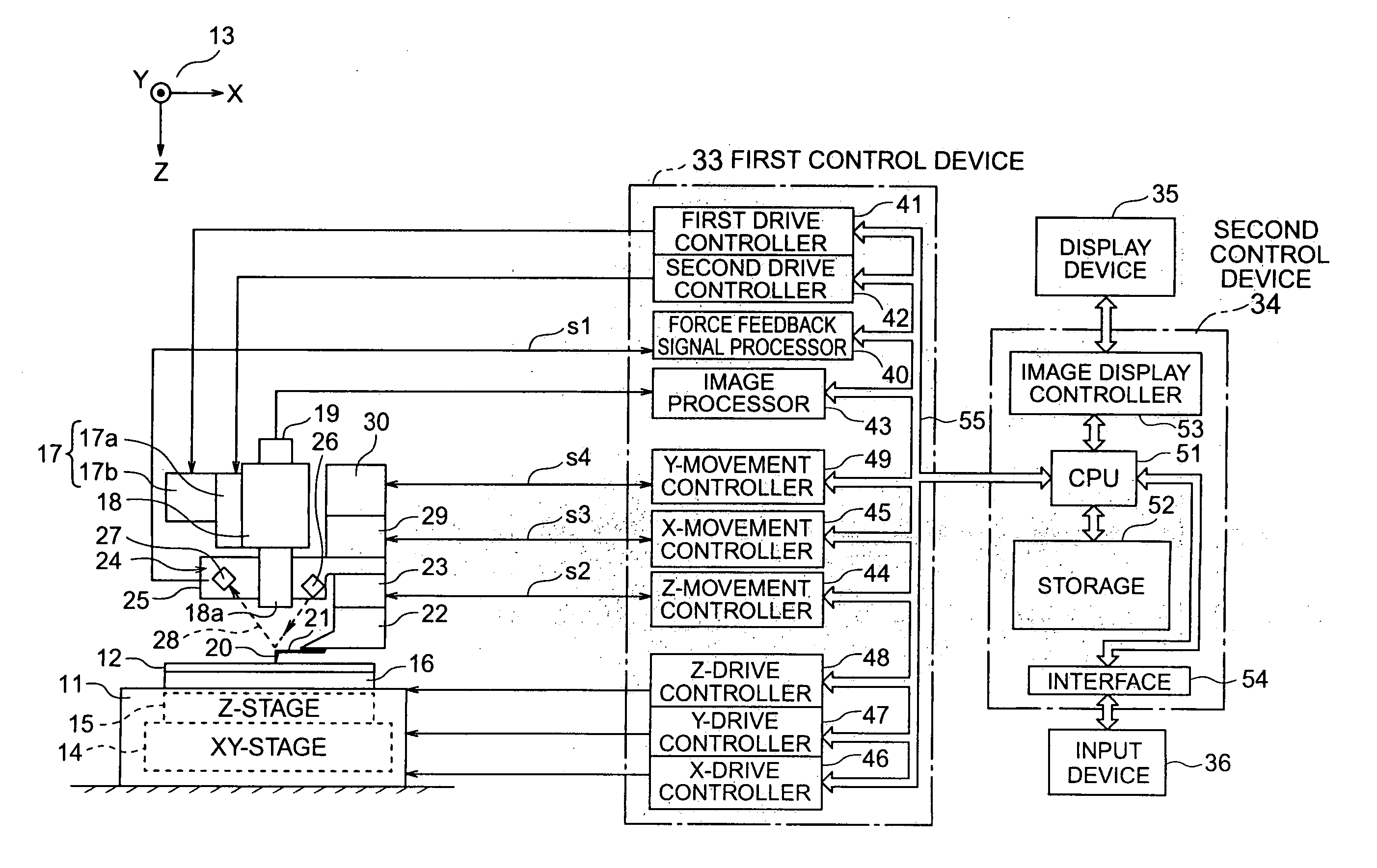
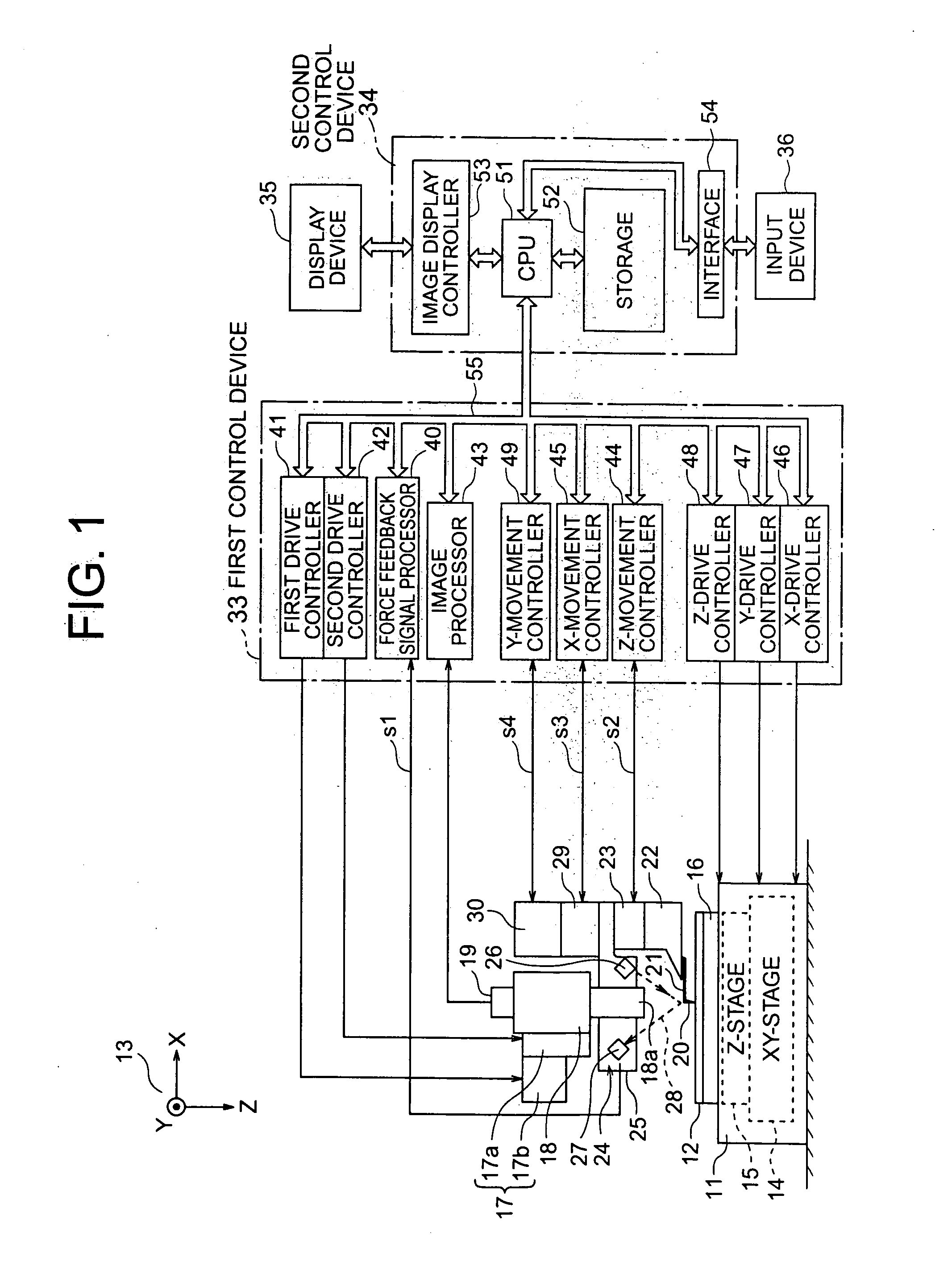
[0019] The overall configuration of a scanning probe microscope (SPM) will be explained with reference to FIG. 1. This scanning probe microscope envisions as a typical example an atomic force microscope (AFM).
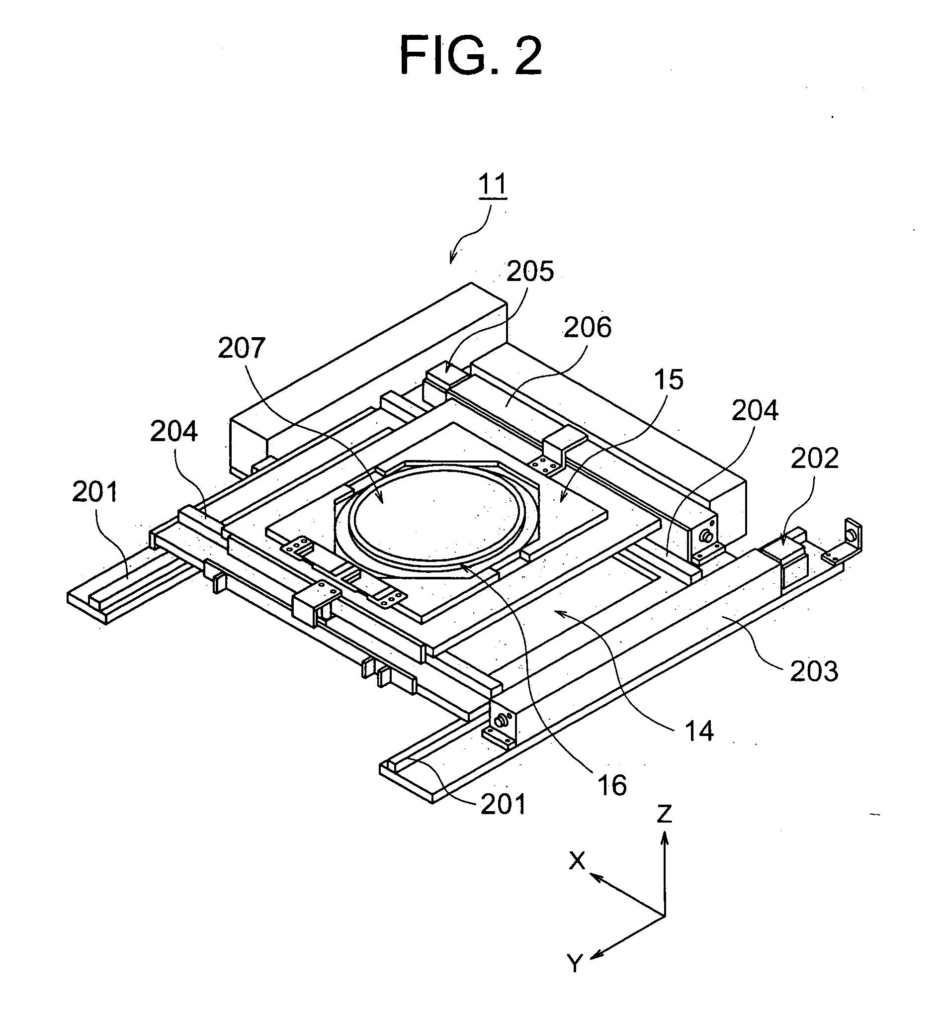
[0020] The bottom part of the scanning probe microscope is provided with a sample stage 11. The sample stage 11 carries a sample 12 on it. The sample stage 11 is a mechanism for changing the position of the sample 12 by a three-dimensional coordinate system 13 comprised of a perpendicular X-axis, Y-axis, and Z-axis. The sample stage 11 is comprised of an XY-stage 14, Z-stage 15, and sample holder 16. The sample stage 11 is usually comprised of a rough movement mechanism causing displacement (change of position) at the sample side. The sample stage 11 has a sample holder 16 on the top surface of which a relatively large area, sheet shaped sample 12 is placed and held. ...
PUM
| Property | Measurement | Unit |
|---|---|---|
| Angle | aaaaa | aaaaa |
| Time | aaaaa | aaaaa |
| Force | aaaaa | aaaaa |
Abstract
Description
Claims
Application Information