Indoor unit for air conditioner

A technology for indoor units and air conditioners, applied in air conditioning systems, applications, household heating, etc., can solve the problems that air cannot be discharged, and air circulation cannot be effectively realized, so as to reduce the contact area, improve air conditioning efficiency, and prevent Effects of foreign body entry

Inactive Publication Date: 2009-12-23
LG ELECTRONICS INC
View PDF5 Cites 9 Cited by
  • Summary
  • Abstract
  • Description
  • Claims
  • Application Information

AI Technical Summary

Problems solved by technology

[0008] In addition, because the direction of the exhaust grill 7 installed at the lower end of the front panel 3 is directed downward, the air cannot be exhausted toward the front of the room.
Therefore, air circulation cannot be effectively achieved

Method used


Image

  • Indoor unit for air conditioner
  • Indoor unit for air conditioner
  • Indoor unit for air conditioner

Examples


Embodiment Construction

[0054]While the invention has been particularly shown and described with reference to exemplary embodiments thereof, it will be understood by those skilled in the art that various changes in form and content may be made without departing from the spirit and scope of the invention as defined by the following claims .

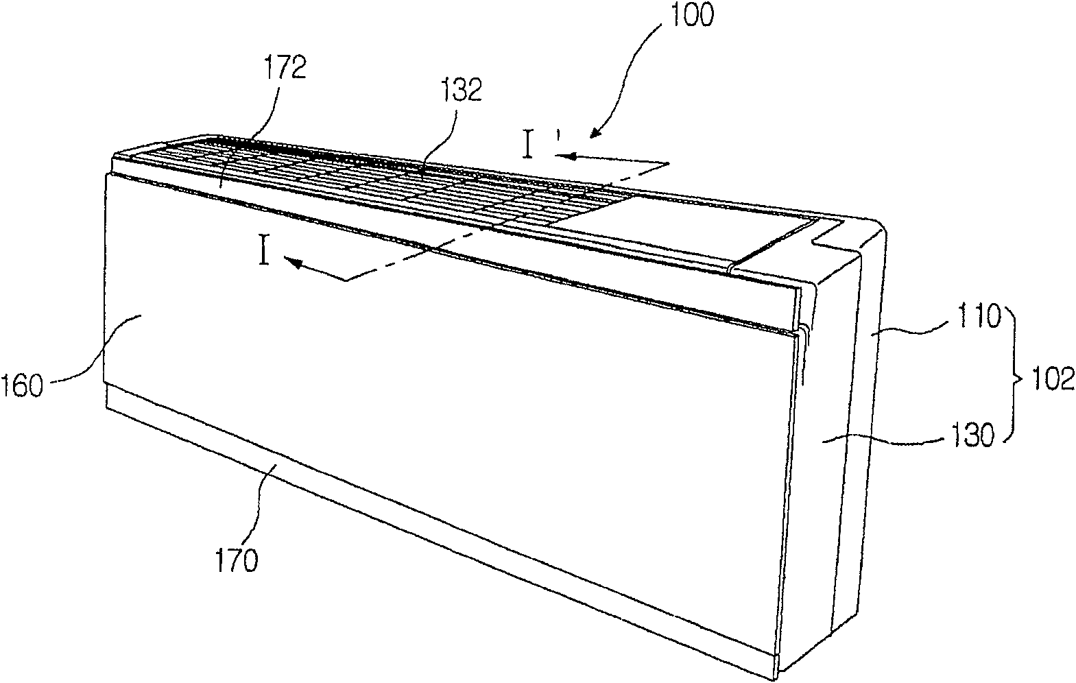
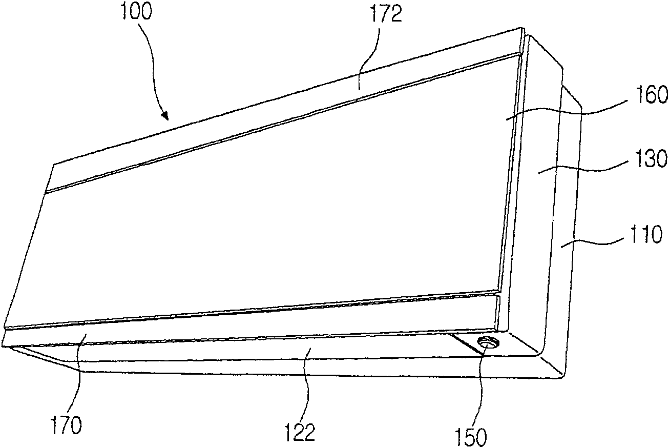
[0055] figure 2 and 3 An indoor unit of an air conditioner according to an embodiment of the present invention is shown.

[0056] refer to figure 2 and 3 , the indoor unit 100 includes a casing 102, a front panel 160 connected to the front of the casing, an exhaust panel 170 slidably connected to the lower end of the front panel 160, a front upper panel 172 slidably connected to the upper end of the front panel 160, and a front panel 172 slidably connected to the casing 102. Lower exhaust vanes.

[0057] The housing 102 includes a main case 110 and a front frame 130 connected to the front of the main case 110 . An intake grill 132 is formed on the top sur...


PUM


Abstract

An indoor unit for an air conditioner includes a housing, a front panel mounted on the front of the housing, an exhaust panel movably mounted on the side of the front panel to selectively open and close an air outlet, and provided on the housing side The part is used to guide the exhaust vane in the exhaust direction.

Description

technical field [0001] The present invention relates to an indoor unit for an air conditioner. Background technique [0002] Generally, an air conditioner is a system for controlling temperature, relative humidity or air purity, and circulating cool air in an enclosed space such as a room. Air conditioners are classified into an integral type in which all components are provided in one unit, and a split type in which an indoor unit and an outdoor unit are separated from each other. [0003] figure 1 A perspective view showing an indoor unit of a conventional air conditioner. [0004] refer to figure 1 , the indoor unit of conventional air conditioner comprises: the main casing that is installed on the interior wall of the room, the front panel 3 that is installed on the main casing 1 front, the air intake grid 5a that forms on the front panel 3, and is installed on the front panel 3 lower end Exhaust grid 7. A display unit 9 for displaying a current operating state and ...

Claims


Application Information

Patent Timeline
Patent Type & Authority Patents(China)
IPC IPC(8): F24F1/00F24F1/48F24F13/08F24F13/28
CPCF24F1/0014F24F13/10F24F2221/26F24F11/52F24F11/74
Inventor 孙良武朱正源朴钟明
Owner LG ELECTRONICS INC
Why Eureka
Try Eureka