Grinding roller mechanism device

A mechanism device and technology of grinding rollers, applied in the field of grinding rollers, can solve the problems of insufficient grinding force and large consumption of metal materials, and achieve the effects of long service life, low wear and simple structure

Inactive Publication Date: 2009-12-30
杨连国
View PDF10 Cites 0 Cited by
  • Summary
  • Abstract
  • Description
  • Claims
  • Application Information

AI Technical Summary

Problems solved by technology

[0002] At present, people use a Raymond mill to crush objects. The grinding roller mechanism of the Raymond mill has a conjugate body, and a vertical pendulum roller is hinged at the end of the conjugate body. When crushing materials, the main shaft rotates at a high speed, driving the conjugate body. The main body rotates, and the pendulum roller presses the material on the millstone for rolling and crushing under the action of centrifugal force. There is only the effect of centrifugal force, there is no gap between the pendulum roller and the millstone, and there is direct contact between the metals, resulting in a large consumption of metal materials. Pressing powder grinding force is the centrifugal force produced when the main shaft rotates, and there is a defect that the grinding force is insufficient; China Patent Office has announced a kind of vertical mill (announcement date: on August 18th, 1993, announcement number CN2140261Y), the The mill borrows the grinding roller mechanism of Raymond Mill, adopts multi-layer grinding roller group, and implements multi-stage crushing on materials, but its grinding force is still the centrifugal force generated when the main shaft rotates, and there is still the defect of insufficient grinding force

Method used


Image

  • Grinding roller mechanism device
  • Grinding roller mechanism device
  • Grinding roller mechanism device

Examples


Embodiment 1

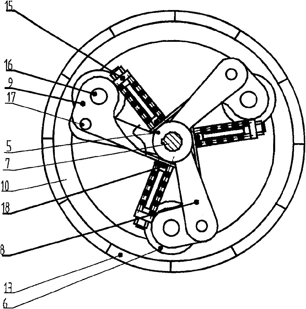
[0013] Embodiment 1: The grinding roller mechanism has a rotor 5, a shaft hole is arranged in the center of the rotor 5, and a rolling working device is hinged on the rotor.

[0014] The rolling working device has a connecting rod 9, which is hinged with the support 8, and one end of the connecting rod is connected with a roller pressure regulator, and the other end is connected with a grinding roller.

[0015] The connecting rod is a crank, and there is a roller gap adjuster between the end of the connecting rod and the rotor.

[0016] The roller pressure regulator is a spring device 15 or a hydraulic device, and the spring device has a spring and a bolt, and the spring is positioned at the outside of the bolt.

[0017] Grinding roller gap adjuster is the limit screw 18 that is connected on the connecting rod.

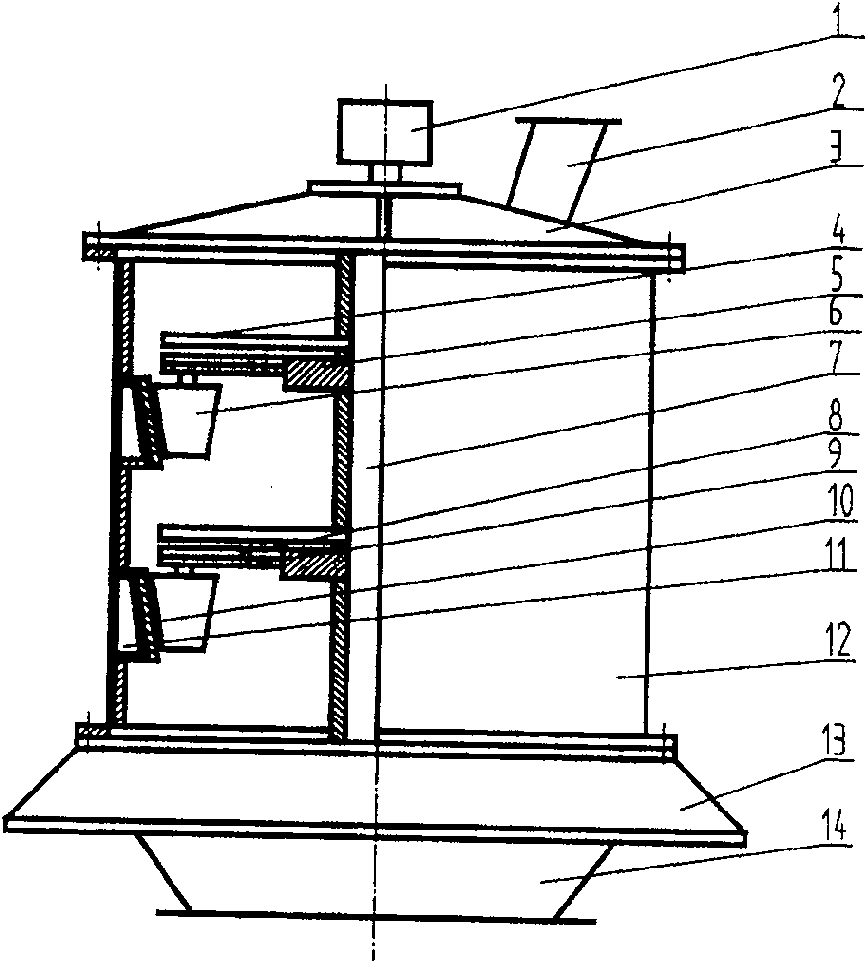
[0018] exist figure 2 , discloses a working device in which the grinding roller mechanism device of the present invention is installed on a grinding roller machine...

Embodiment 2

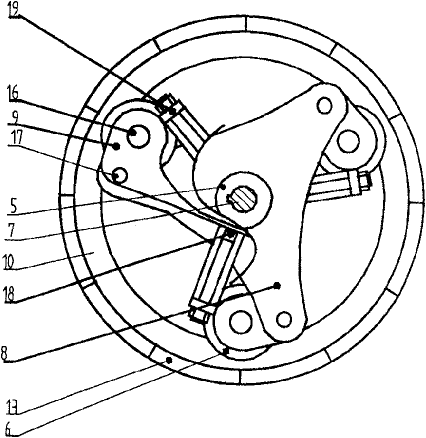
[0020] Embodiment 2: The roller pressure regulator is a hydraulic device, and the hydraulic device 19 is a hydraulic rod. Others are the same as embodiment 1, omitted.

Embodiment 3

[0021] Embodiment 3: The roller pressure regulator is a spring device, the spring device has a spring and a sleeve, and the spring is located inside the sleeve. Others are the same as in the embodiment, omitted.


PUM


Abstract

A grinding roller mechanism has a rotor with a central axle hole, a roller pressing unit with a pressure regulator and a connecting rod linked between said pressure regulator and grinding roller, and a regulating and limiting screw for regulating the gap between grinding roller and grinding disc.

Description

technical field [0001] The invention relates to a grinding roller of a roller mill, in particular to a grinding roller mechanism device. Background technique [0002] At present, people use a Raymond mill to crush objects. The grinding roller mechanism of the Raymond mill has a conjugate body, and a vertical pendulum roller is hinged at the end of the conjugate body. When crushing materials, the main shaft rotates at a high speed, driving the conjugate body. The main body rotates, and the pendulum roller presses the material on the millstone for rolling and crushing under the action of centrifugal force. There is only the effect of centrifugal force, there is no gap between the pendulum roller and the millstone, and there is direct contact between the metals, resulting in a large consumption of metal materials. Pressing powder grinding force is the centrifugal force produced when the main shaft rotates, and there is a defect that the grinding force is insufficient; China Pat...

Claims


Application Information

Patent Timeline
Patent Type & Authority Patents(China)
IPC IPC(8): B02C15/08
Inventor 杨连国
Owner 杨连国
Why Eureka
Try Eureka