
Switch system with control device

A control device and switching system technology, applied in the system field, can solve problems such as inability to guarantee, and achieve the effect of improving support

Inactive Publication Date: 2009-12-30
SIEMENS AG
View PDF7 Cites 0 Cited by
  • Summary
  • Abstract
  • Description
  • Claims
  • Application Information

AI Technical Summary

Problems solved by technology

Therefore, there is no guarantee that the corresponding switching member is actually ready for operation with the emergency shutdown current circuit closed

Method used


Image

  • Switch system with control device
  • Switch system with control device
  • Switch system with control device

Examples


Embodiment Construction

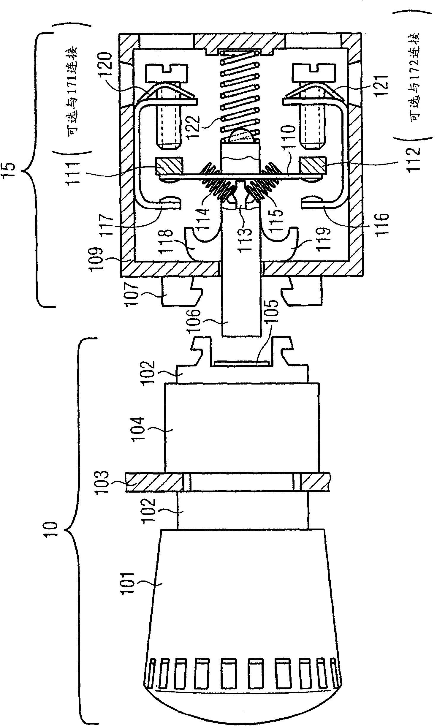
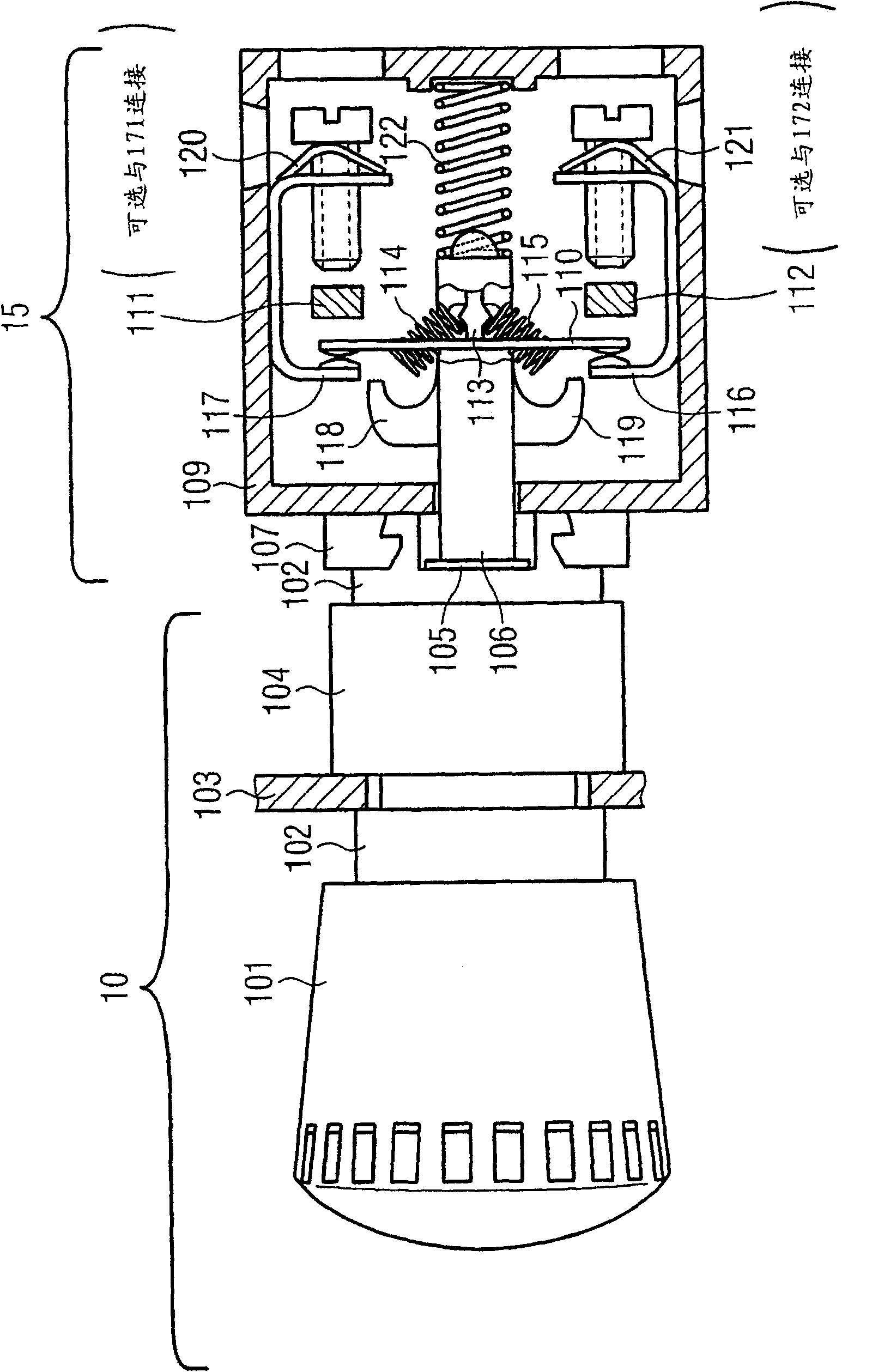
[0030] Figure 1AThe control device 10 is shown already mounted on a control board or control panel 103 . The main body 102 of the control device 10 passes through an opening in a control board or disc 103 and is then fastened together with a fixed support 104 . The control device 10 comprises an actuator 101, the movement of which causes an actuator plunger 105 to move. The actuator plunger 105 and the actuator 101 may be constructed of one piece or may be connected to each other or otherwise arranged such that the actuator plunger 105 may follow the movement of the actuator 101 .

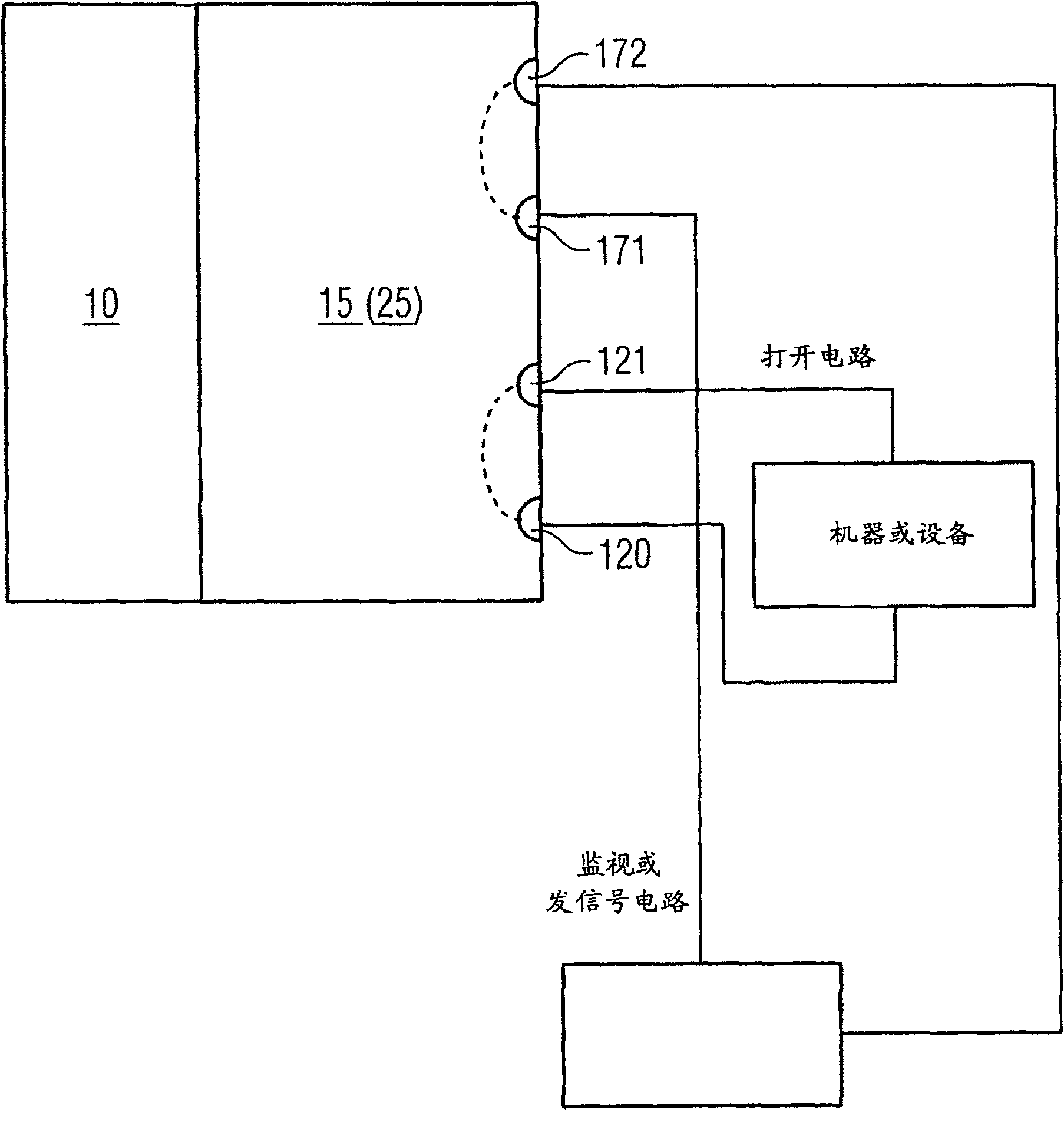
[0031] Figure 1A The switch member 15 is also shown. The switch member 15 includes a first terminal 120 and a second terminal 121 , and optionally a third terminal 171 and a fourth terminal 172 .

[0032] The first terminal 120 and the second terminal 121 are connected to an open circuit; if the first terminal 120 and the second terminal 121 are electrically connected to each other and if the...


PUM


Abstract

A system includes a control device including an actuator, a movement of which is adapted to cause a movement of an actuator plunger; and a switching element. The switching element includes a switch slide adapted to follow a movement of the actuator plunger; a first terminal and a second terminal; contacting members adapted to connect the first terminal to the second terminal; and contact breaking member adapted to disconnect the first terminal from the second terminal in response to an inward displacement of the switch slide exceeding a first distance. The switching element further includes a jump system, responsive to displacement of the switch slide, adapted to bring the contacting members together to connect the first terminal to the second terminal if the inward displacement of the switch slide exceeds a second distance that is less than the first distance.

Description

technical field [0001] The described embodiments relate to the technical field of control devices and switching members, and in particular to a system comprising a control device and a switching member, wherein the control device includes an actuator whose movement is adapted to cause actuation The plunger of the switch moves, and the switch component includes a switch slide bar, a first terminal and a second terminal, a contact element, and a contact breaking element. Background technique [0002] Many machines and powered equipment can be controlled through controls, especially controls like buttons or mode switches. Controls are usually built modularly and include actuators, fixed parts such as ring nuts or assembly holders so that they can be connected to One or more switch members are connected. The controls and switch members can then be mounted eg on a control board or panel. [0003] The actuator can usually be mounted on a control board or control panel by passin...

Claims


Application Information

Patent Timeline
Patent Type & Authority Patents(China)
IPC IPC(8): H01H13/02H01H13/12H01H13/20H01H13/28
CPCH01H13/506H01H2300/028H01H3/022H01H3/54H01H1/20
Inventor 约瑟夫·谢尔鲁道夫·齐默尔曼
Owner SIEMENS AG
Learn More