Vehicle horn driving circuit

A driving circuit and speaker technology, which is applied to vehicle components, sounding devices, instruments, etc., can solve problems such as poor sounding, and achieve the effects of suppressing voltage changes, avoiding large-scale, and reliable sounding

Inactive Publication Date: 2010-01-13
HONDA MOTOR CO LTD
View PDF2 Cites 0 Cited by
  • Summary
  • Abstract
  • Description
  • Claims
  • Application Information

AI Technical Summary

Problems solved by technology

[0006] However, although the AC horn emits sound by repeating the operation of attracting the film to the exciting coil side and separating the film from the exciting coil by an AC current, as described above, since the AC horn is connected in parallel to the AC regulator, If the rotation speed of the motor is in the high-speed rotation range, the current that exerts the electromagnetic force that attracts the film in the excitation coil of the AC speaker becomes a pulsating current due to the action of the AC regulator and continues to flow, so there is a possibility of poor sound generation.

Method used


Image

  • Vehicle horn driving circuit
  • Vehicle horn driving circuit
  • Vehicle horn driving circuit

Examples


Embodiment Construction

[0019] Next, an embodiment of the present invention will be described based on an embodiment of the present invention shown in the drawings.

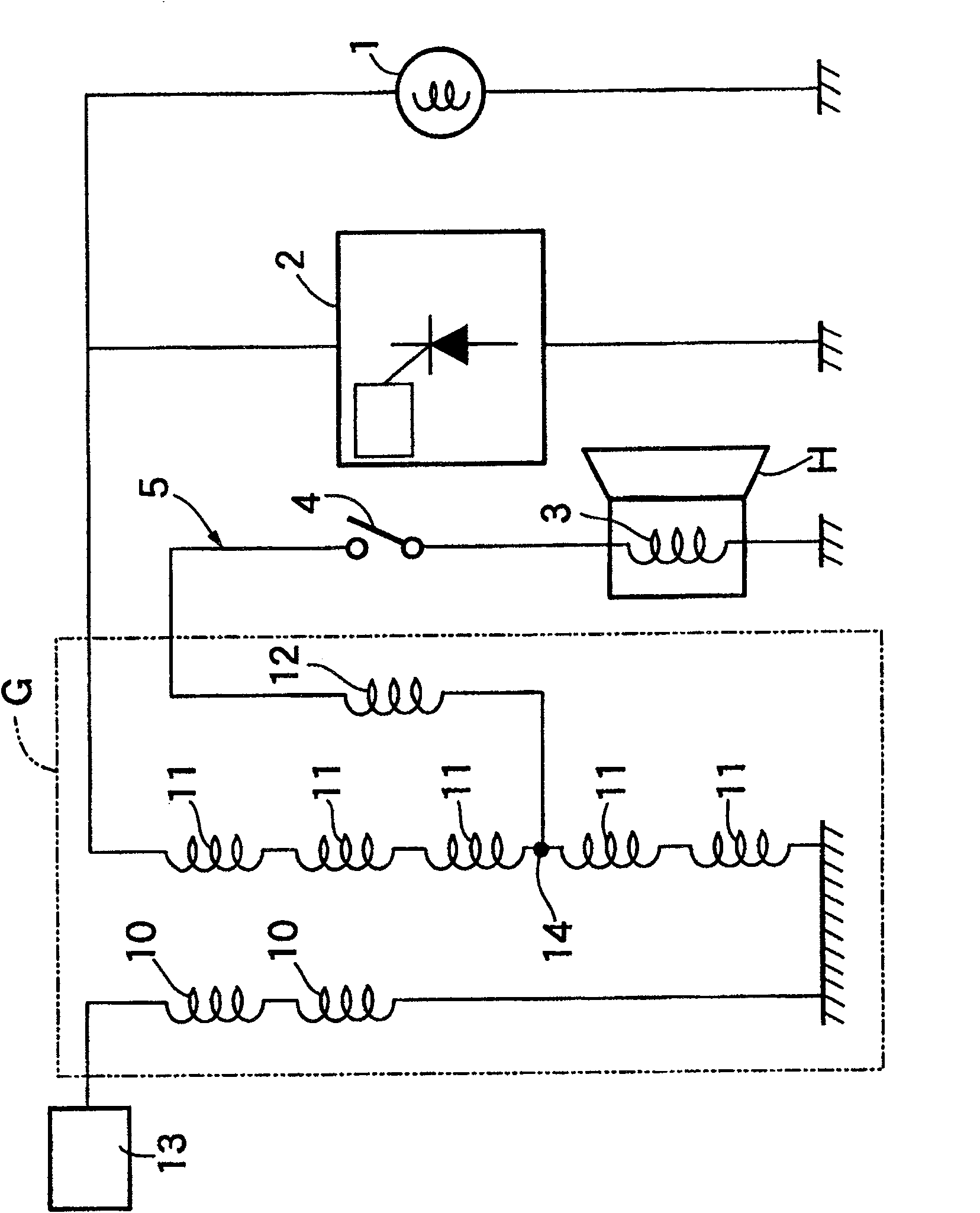
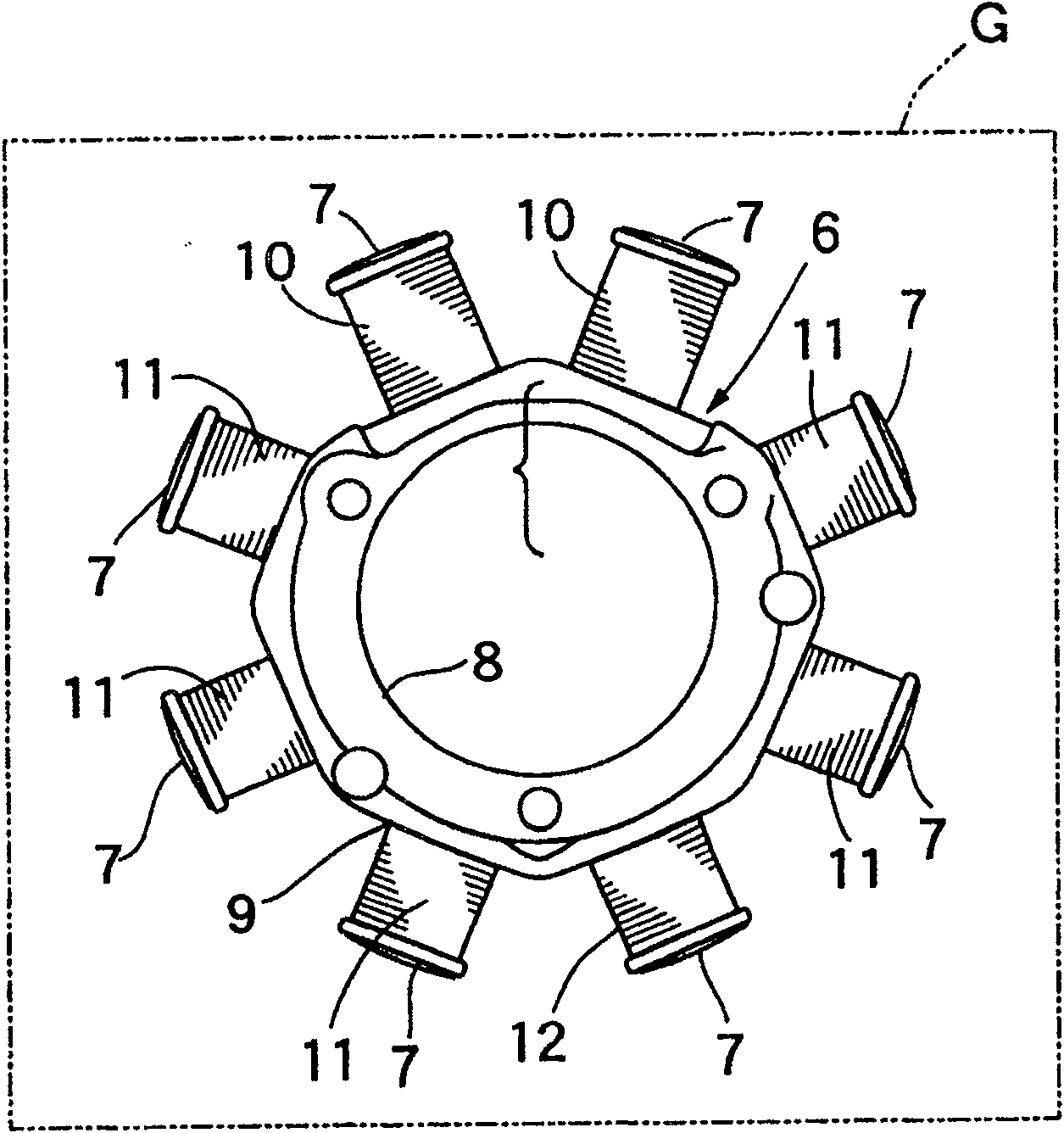
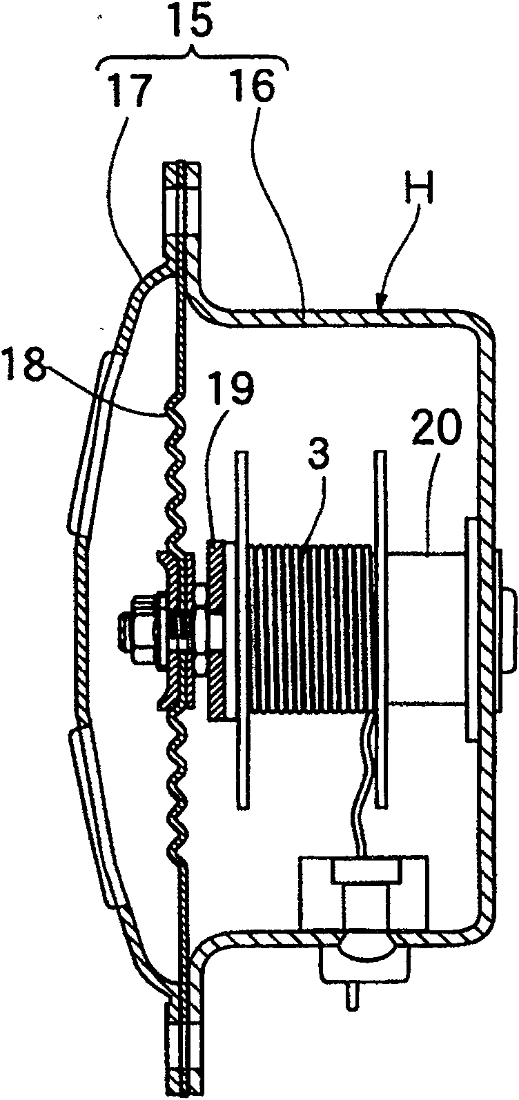
[0020] figure 1 It is a circuit diagram containing an AC speaker, figure 2 It is a front view of a stator included in a multi-pole alternator, image 3 is the longitudinal sectional view of the AC horn, Figure 4 It is a graph showing the field coil current supplied to the AC speaker in the rest state of the AC regulator in the low-speed rotation region when the electric load and the AC speaker are connected in parallel, Figure 5 It is a diagram showing the excitation coil current supplied to the AC speaker in the operating state of the AC regulator in the medium-speed rotation region when the electric load and the AC speaker are connected in parallel, Figure 6 It is a graph showing the field coil current supplied to the AC speaker in the operating state of the AC regulator when the electric load and the AC speaker are connected i...


PUM


Abstract

A horn electrical energization circuit 5 including an AC type horn H is connected to a multi-pole type AC power generator G while being independent from a circuit to be controlled with an AC regulator 2.

Description

technical field [0001] The present invention relates to an improvement in a vehicle horn drive circuit for driving an AC horn by power generated by an engine driven multi-pole alternator. Background technique [0002] Patent Document 1 discloses a vehicle horn drive circuit in which an AC horn is connected to one end of a power generation coil included in a multi-pole alternator via a half-wave rectification unit. [0003] Patent Document 1 Publication No. 63-42025 [0004] In the prior art described above, in order to prevent the natural frequency of the vibrating plate of the AC horn from mismatching with the frequency of the AC current output from the multi-pole alternator, the horn cannot emit sound especially in the high-speed rotation region of the motor. , and the AC current is provided to the excitation coil of the horn after half-wave rectification. [0005] On the other hand, in order to convert the AC voltage obtained by the multi-pole alternator into a stable A...

Claims


Application Information

Patent Timeline
Patent Type & Authority Patents(China)
IPC IPC(8): B60Q5/00G10K9/13
Inventor 柳泽毅中岛广幸石塚诚
Owner HONDA MOTOR CO LTD
Why Eureka
Try Eureka