
Fiber reinforcement for making an elongate mechanical part out of composite material

a technology of composite materials and mechanical parts, which is applied in the direction of weaving, other domestic objects, transportation and packaging, etc., can solve the problems of composite material poor impact strength, high risk of delamination, and parts that form the interface with other parts of landing gear also being over-dimensioned, so as to offset the discontinuity of materials and improve the ability to withstand hammering

Active Publication Date: 2015-08-27
SN DETUDE & DE CONSTR DE MOTEURS DAVIATION S N E C M A +2
View PDF4 Cites 10 Cited by
  • Summary
  • Abstract
  • Description
  • Claims
  • Application Information

AI Technical Summary

Benefits of technology

The invention proposes a mechanical part made of composite material that improves its ability to withstand hammering (both compression and traction forces). It also helps to offset material discontinuity away from a highly-stressed zone, leading to a saving in weight and a more compact part.

Problems solved by technology

However, making such parts out of composite material raises various problems.
In particular, given the limitations of composite materials concerning their ability to withstand hammering, the lugs of such parts are generally over-dimensioned, giving rise to the metal parts constituting interfaces with other parts of the landing gear also being over-dimensioned.
Furthermore, such parts made of composite material present poor impact strength and a high risk of delamination, i.e. of their fiber layers separating, as a result of the repeated forces to which the part is subjected.
Finally, the costs of fabricating such parts are high.

Method used


Image

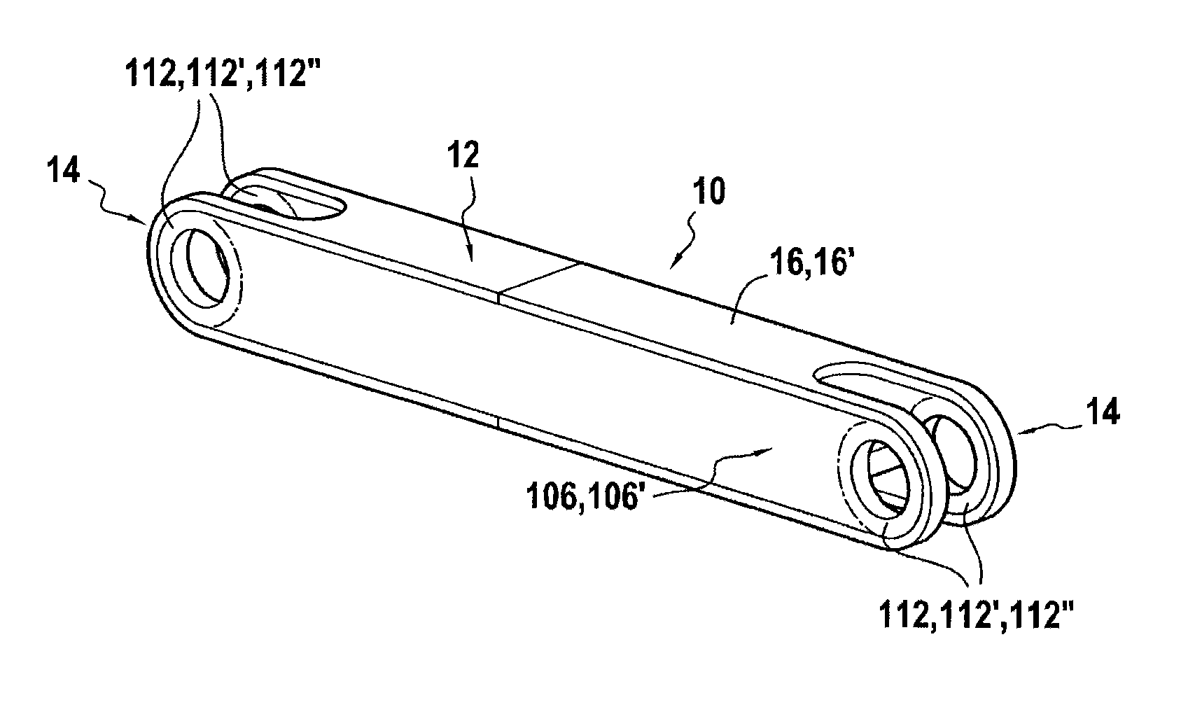
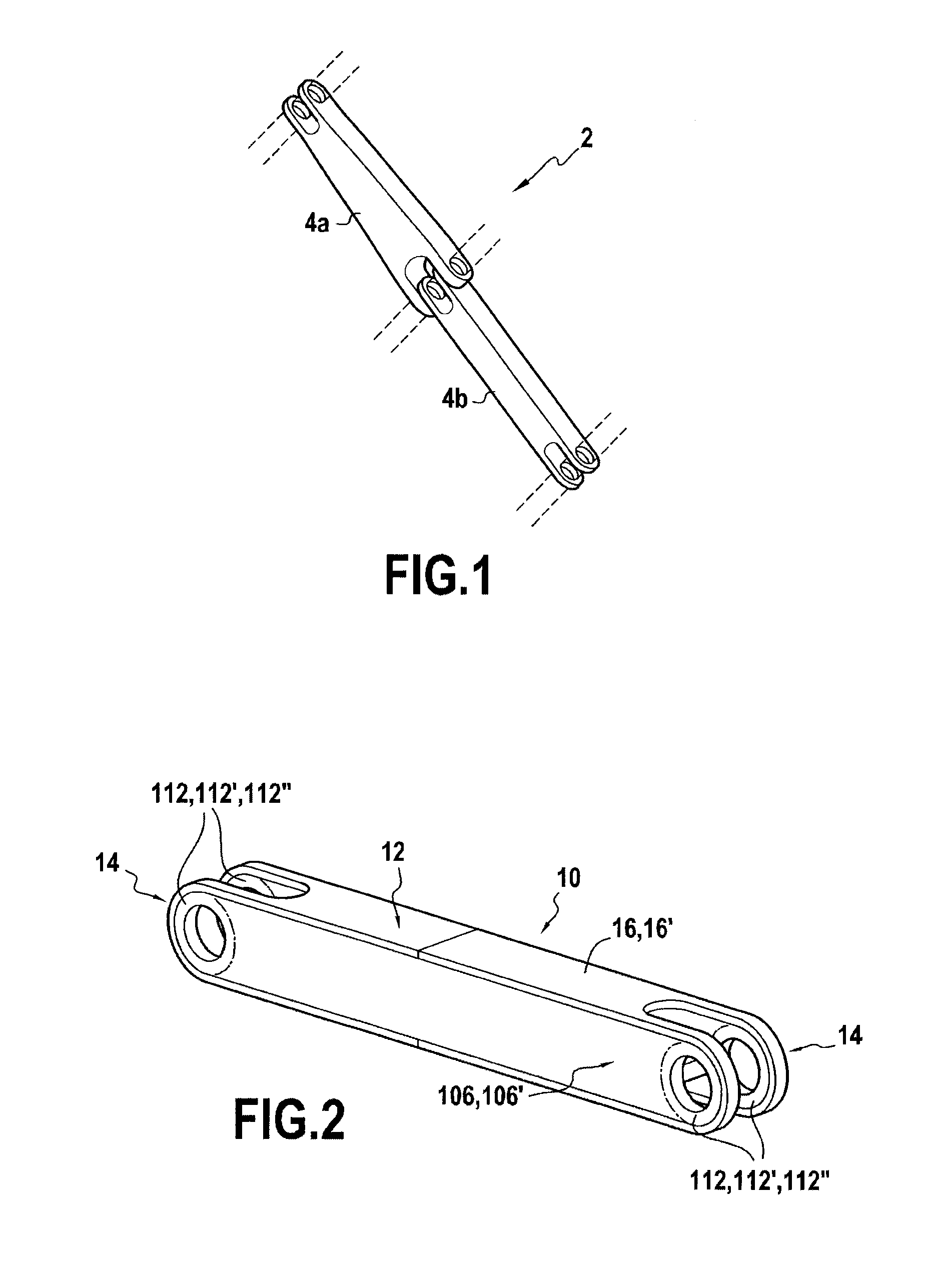
  • Fiber reinforcement for making an elongate mechanical part out of composite material
  • Fiber reinforcement for making an elongate mechanical part out of composite material
  • Fiber reinforcement for making an elongate mechanical part out of composite material

Examples


first embodiment

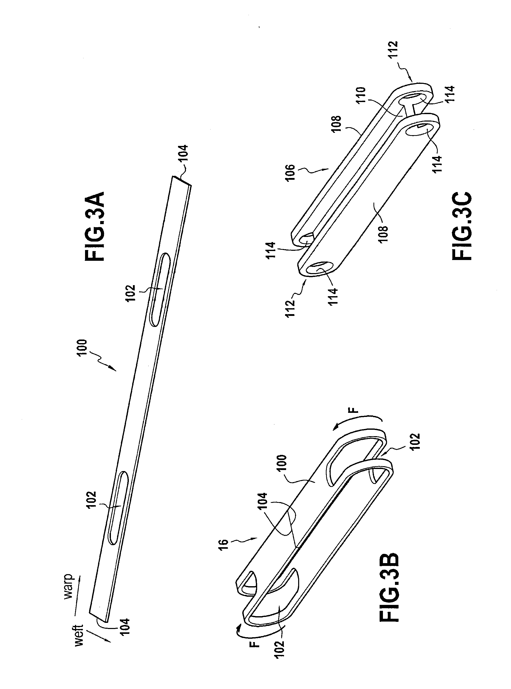
[0032]FIGS. 3A to 3C show various steps of obtaining such fiber reinforcement, in the invention.

[0033]In this first embodiment, the peripheral fiber structure for making the belt is obtained by three-dimensionally weaving a fiber blank as shown in FIG. 3A. This fiber blank is in the form of a strip 100 having a plurality of layers of warp yarns extending in the length direction of the strip and interlinked by weft yarns (the warp and weft directions being shown in FIG. 3A).

[0034]Openings 102 of oblong shape are made in the strip, being oriented in the length direction, and passing through the strip in the thickness direction. By way of example, such openings are made by cutting with a water jet. The resulting strip 100 is then looped as shown by arrows F (FIG. 3B) so as to join together the free ends 104 and form a loop. These ends 104 are then joined together, e.g. by stitching, by adhesive, or by any other appropriate technique.

[0035]Once the strip 100 has been looped, the periphe...


PUM

PropertyMeasurementUnit
lengthaaaaaaaaaa
mechanicalaaaaaaaaaa
lateral forcesaaaaaaaaaa

Abstract

The invention relates to fiber reinforcement for making an elongate mechanical part (10) out of composite material having a lug (14) at at least one end for receiving a pin for making a pivot connection with another part, the fiber reinforcement being made from a central fiber structure (106; 106′) for forming a core that is obtained by three-dimensional weaving, from a peripheral fiber structure (16; 16′) that is to form a belt surrounding the central structure so as to form at least one empty cylindrical space in the lug of the part, and from at least one annular fiber structure (112; 112′; 112″) that is to form a ring that is formed inside the empty space provided between the central structure and the peripheral structure.

Description

BACKGROUND OF THE INVENTION[0001]The present invention relates to the general field of making an elongate mechanical part out of composite material, such a part having a lug at at least one of its ends for receiving a pin to provide a pivot connection with another part, and being stressed in operation both in traction and in compression.[0002]A nonlimiting example of an application of the invention lies in making side-braces for landing gear.[0003]A landing gear side-brace serves to take up lateral forces exerted on the landing gear and to keep it deployed after making contact with the ground. Typically, a side-brace comprises two arms that are hinged to each other and to other parts of the landing gear via their ends, by pivot connections.[0004]In operation, such a mechanical part is subjected to high levels of mechanical force, mainly in compression and in traction, which forces are oriented along the longitudinal axis of the part (i.e. the axis passing through both ends of the pa...

Claims


Application Information

Patent Timeline
Patent Type & Authority Applications(United States)
IPC IPC(8): B64C25/10B32B5/22B32B5/02
CPCB64C25/10B32B5/024B32B2605/18B32B2250/03B32B2250/20B32B5/22B29L2031/3076B29C70/48B29C70/222B29C70/24F16C7/026Y10T442/3528B29C70/304B29L2031/06
Inventor LECLERCQ, SYLVAINDAMBRINE, BRUNO JACQUES GERARDCOUPE, DOMINIQUE MARIE CHRISTIAN
Owner SN DETUDE & DE CONSTR DE MOTEURS DAVIATION S N E C M A
Learn More