
Assembling structure of cabinet

A combined structure and cabinet technology, applied in combined furniture, home appliances, applications, etc., can solve the problems of cabinet 1 falling, lockers cannot be set stably, time-consuming, etc., and achieve the effect of convenient assembly

Inactive Publication Date: 2010-01-20
陈凤桂
View PDF7 Cites 0 Cited by
  • Summary
  • Abstract
  • Description
  • Claims
  • Application Information

AI Technical Summary

Problems solved by technology

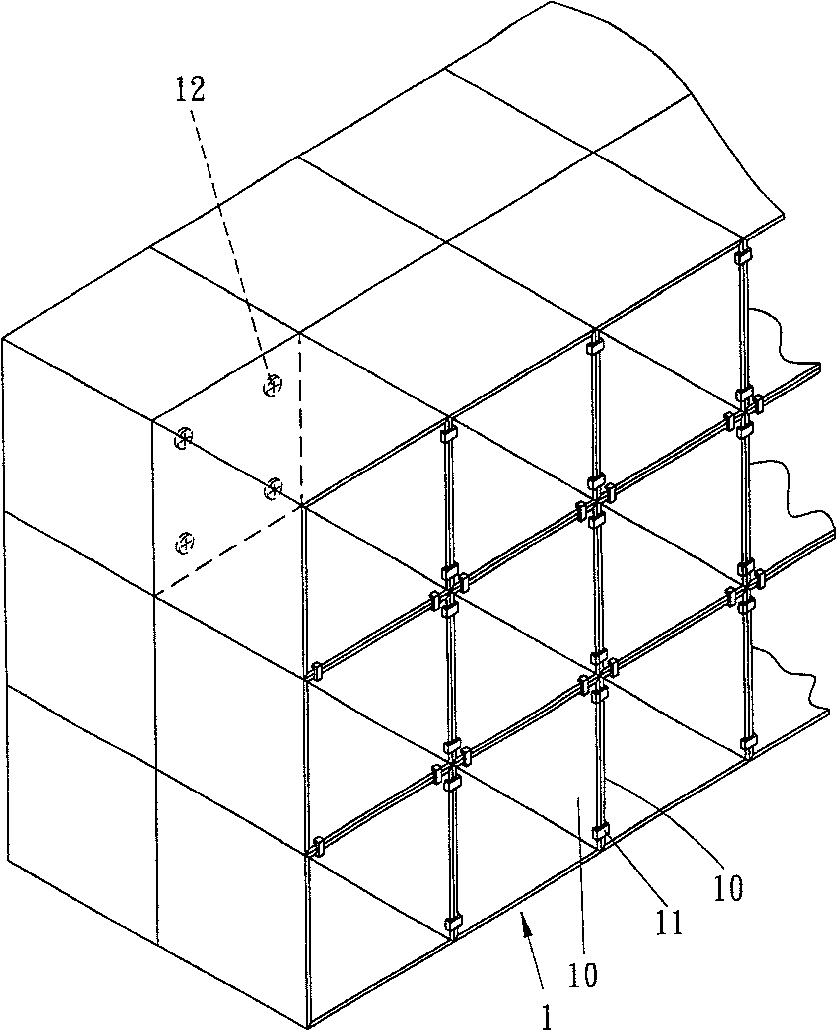
[0002] Most of the general lockers are to connect the boards 10 (bottom board, left side board, right side board, top board and back board) to each other, glue or nail them to form a fixed cabinet body 1, and if you want to assemble them into a Large area lockers (such as figure 1 As shown), the cabinets 1 are stacked against each other, and then the ㄇ-shaped buckle clip 11 is used to fasten the four sides of the joint of the two boards 10 to complete the assembly; however, this kind of ㄇ-shaped buckle clip 11. When the locker with fastening combination is shaken by impact, because the cabinet body 1 is only fastened and combined at the front, and there is no positioning setting at the rear, the ㄇ-shaped buckle clip 11 is easy to fall off, making the locker unable to be installed stably. It is very dangerous that the cabinet body 1 will fall due to the falling of the ㄇ-shaped buckle clip 11. When the cabinet body 1 with two phases facing away is to be positioned, most of the cabinet body 1 is positioned with the two phases facing away by the fixed component 12. The backboard bodies 10 facing to each other are screwed and fixedly connected to increase the stability of their assembly, but this assembly method is extremely time-consuming and labor-intensive; therefore, the inventor considers that the prior art lockers have the above-mentioned shortcomings, designed the invention

Method used


Image

  • Assembling structure of cabinet
  • Assembling structure of cabinet
  • Assembling structure of cabinet

Examples


Embodiment Construction

[0013] Relevant present invention is for reaching above-mentioned purpose of use and effect, the technical means that adopts, presents preferred and feasible embodiment hereby, and cooperates as shown in the accompanying drawings, explains in detail as follows:

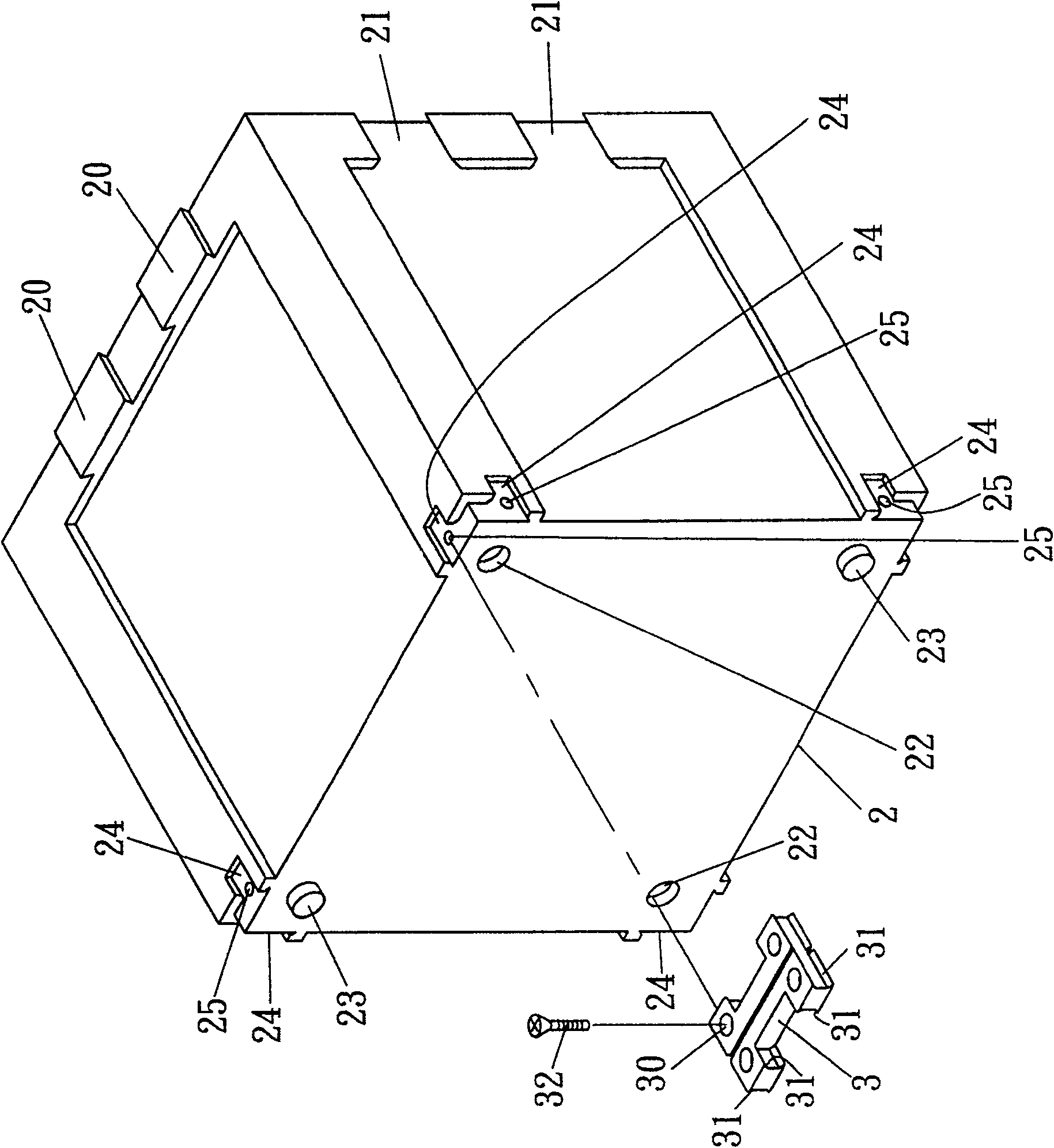
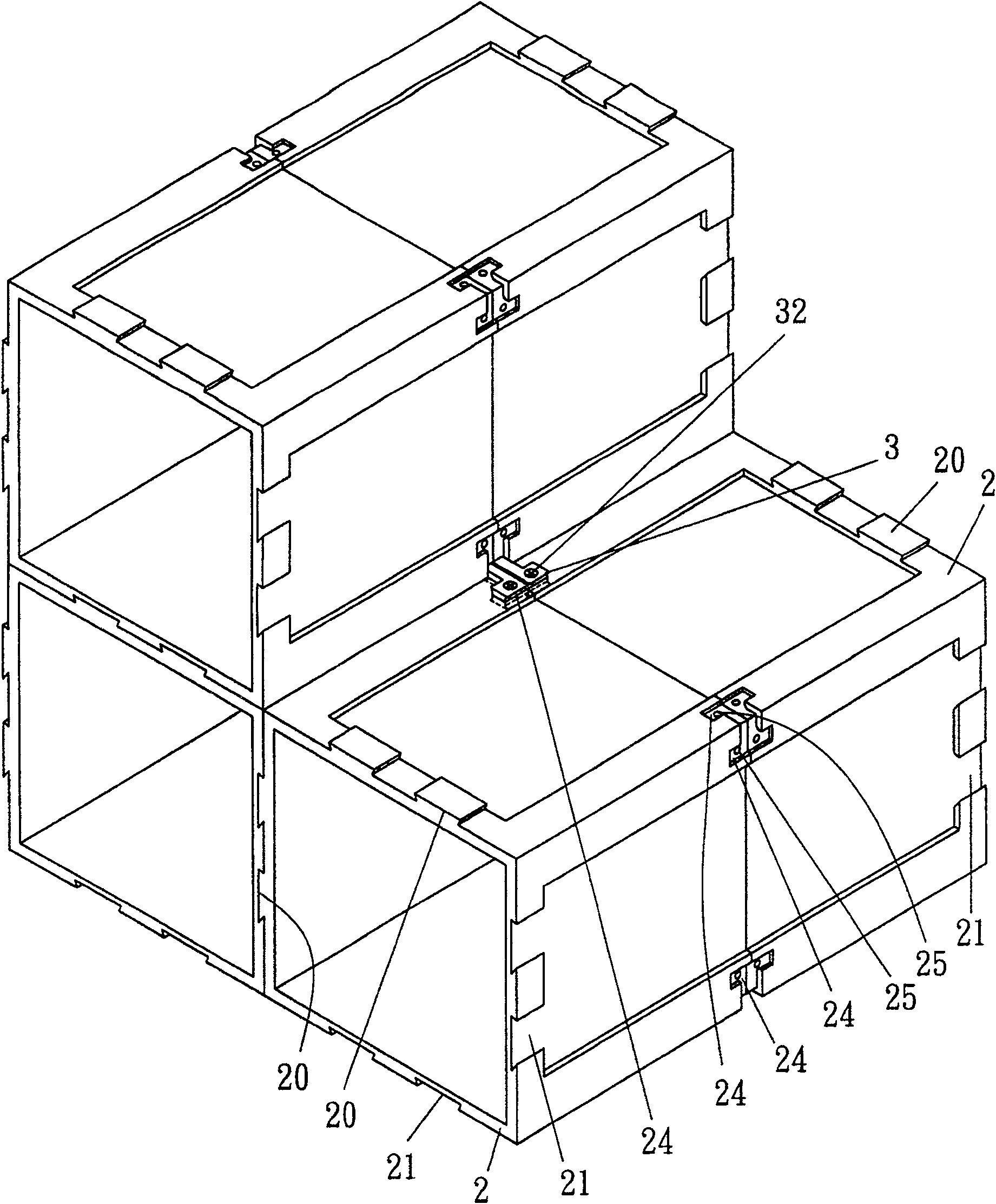
[0014] First, see figure 2 , image 3 As shown, two dovetail seats 20 are protruded on the adjacent two peripheral walls of the cabinet body 2, and two dovetail grooves 21 are formed on the other adjacent two peripheral walls. There are perforations 22 and protruding columns 23, and an L-shaped dovetail groove-shaped inlay 24 is respectively provided on two adjacent planes on the rear end corner of the cabinet body 2, and a screw hole 25 is provided in the inlay 24; The latch 3 is inserted at the rear end of the cabinet body 2, the positioning latch 3 is I-shaped, and each of its four ends is provided with a perforation 30, and the top and bottom surfaces of the four ends of the positioning latch 3 are convexly prov...


PUM


Abstract

An assembly cabinet structure features that adjacent two walls have the dove-tail tenons, adjacent another two walls have mortis slots, the back corners of cabinet have L-shaped embedding slots, and the I-shaped locating pins with the convex embedding bodies on its top surface and bottom surface for matching with said embedding slots. Its advantage is convenient and firm assembly.

Description

technical field [0001] The present invention relates to a combined structure of a cabinet, in particular to a structure in which cabinet bodies that are docked and back-to-back are assembled stably and reliably into a large-area combined cabinet. Background technique [0002] Most of the general lockers are to connect the boards 10 (bottom board, left side board, right side board, top board and back board) to each other, glue or nail them to form a fixed cabinet body 1, and if you want to assemble them into a Large area lockers (such as figure 1 As shown), the cabinets 1 are stacked against each other, and then the ㄇ-shaped buckle clip 11 is used to fasten the four sides of the joint of the two boards 10 to complete the assembly; however, this kind of ㄇ-shaped buckle clip 11. When the locker with fastening combination is shaken by impact, because the cabinet body 1 is only fastened and combined at the front, and there is no positioning setting at the rear, the ㄇ-shaped buck...

Claims


Application Information

Patent Timeline
Patent Type & Authority Patents(China)
IPC IPC(8): A47B87/00
Inventor 陈凤桂
Owner 陈凤桂
Learn More