
Double-camera calibrating method in three-dimensional scanning system

A dual-camera, three-dimensional scanning technology, used in image communication, image analysis, image data processing, etc., can solve problems such as no imaging center correction

Inactive Publication Date: 2010-01-20
海安江理工技术转移中心有限公司 +1
View PDF2 Cites 0 Cited by
  • Summary
  • Abstract
  • Description
  • Claims
  • Application Information

AI Technical Summary

Problems solved by technology

The disadvantage is that in this method, the lateral spacing and vertical spacing of the photosensitive elements in the CCD array are considered to be known, and the imaging center is not corrected.

Method used


Image

  • Double-camera calibrating method in three-dimensional scanning system
  • Double-camera calibrating method in three-dimensional scanning system
  • Double-camera calibrating method in three-dimensional scanning system

Examples


Embodiment Construction

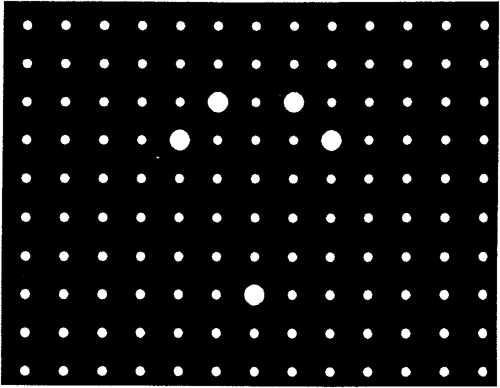
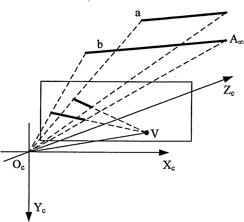
[0055] The calibration of the dual cameras in the 3D scanning system includes: first calibrating the distortion coefficient; then using the distortion coefficient to perform image correction on the captured image, and combining the ideal pinhole perspective model, calibrating the internal parameters of the camera, where the internal parameters of the camera mainly include the imaging center, The inter-axis tilt factor and equivalent focal length; finally, the external parameters of the left and right cameras are calibrated according to the internal parameters of the camera, and the relative external parameters of the left and right cameras are further calibrated by using the external model of the dual camera, which is characterized by:

[0056] (1) Calibration of distortion coefficient

[0057] Using a set of marker dots located on parallel lines on the calibration plate, and according to the basic principle of straight line perspective projection, use the parallel lines to pro...


PUM


Abstract

This invention relates to a double-vidicon calibration method in a three-D scan system including: calibrating aberration coefficient first, then correcting the pick-up image utilizing the aberration coefficient to calibrate the internal parameter of the vidicon combined with an deal pinhole perspective model, and the parameter includes an imaging center, slant factors among axeses and equivalent focuses, finally calibrating the outside parameters of the right and left vidicons based on the internal parameter and further utilizing the outer model of the double vidicons to calibrate relative outside parameters of the two vidicons to get the internal and outside parameters.

Description

technical field [0001] The invention relates to the problem of calibrating dual cameras in a vision system, in particular to a method for calibrating dual cameras in a three-dimensional scanning system. Background technique [0002] One of the basic tasks of computer vision is to calculate the three-dimensional information of objects in the field of view from the images captured by the camera, so as to reconstruct and recognize three-dimensional objects. The relationship between the three-dimensional geometric information of the surface point of the object and its corresponding point on the image is determined by the imaging model of the camera. The process of establishing this geometric model is actually the process of solving the camera parameters. Therefore, the calibration of camera parameters is the premise and key of this modeling process. The process of solving camera parameters is called camera calibration. [0003] A more general camera imaging model is described ...

Claims


Application Information

Patent Timeline
Patent Type & Authority Patents(China)
IPC IPC(8): G06T7/00H04N17/00
Inventor 达飞鹏钱志峰
Owner 海安江理工技术转移中心有限公司
Learn More