Forced pan unloading mechanism for rotary filter cloth and forced pan unloading method

A filter cloth and filter cake technology, which is applied in the field of filter cloth cake unloading mechanism and method of filter press, can solve the problems of high manufacturing cost, inability to realize automatic forced cake unloading, complicated filter cloth walking mechanism, etc., to ensure cleanliness Effect

Active Publication Date: 2010-01-27
杭州兴源环保设备有限公司
View PDF3 Cites 0 Cited by
  • Summary
  • Abstract
  • Description
  • Claims
  • Application Information

AI Technical Summary

Problems solved by technology

Its disadvantages: first, the filter cloth walking mechanism is complicated, and the manufacturing cost is high; second, because the diaphragm filter cloth is in a stationary state, it is impossible to realize automatic forced cake unloading

Method used


Image

  • Forced pan unloading mechanism for rotary filter cloth and forced pan unloading method
  • Forced pan unloading mechanism for rotary filter cloth and forced pan unloading method
  • Forced pan unloading mechanism for rotary filter cloth and forced pan unloading method

Examples


Embodiment 1

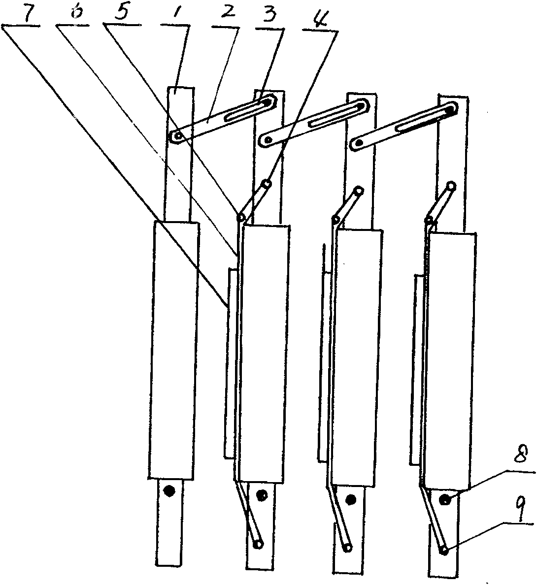
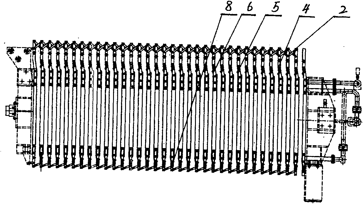
[0012] Embodiment 1: with reference to attached Figure 1~3 . Filter cloth rotating forced cake unloading mechanism, the adjacent diaphragm filter plates in the multiple diaphragm filter plates 1 located between the thrust plate and the pressing plate are connected by the guide groove pin plate 2, and the two ends of the guide groove pin plate 2 are pin holes 10 and a pin hole is communicated with guide groove 3, and the structure that connects is prior art, as electric sliding door structure. The plurality of diaphragm filter plates 1 are driven by the pressing plate to open or close the plurality of diaphragm filter plates, and the upper and lower end lugs of the plurality of diaphragm filter plates 1 are respectively pierced with an upper suspension rod 4 and a lower suspension rod 9 (also Be exactly bar), upper and lower suspenders 4 and 9 rotate around their shaft holes or are sleeved with bearings and the bearings are located in the upper and lower end lug bearing holes...

Embodiment 2

[0013] Embodiment 2: On the basis of Embodiment 1, the filter cloth is rotated and forced to unload the cake method, and the multiple interconnected diaphragm filter plates located between the thrust plate and the compression plate are driven by the compression plate to drive the plurality of diaphragm filter plates. The plates are opened one by one, and the multiple membrane filter cloths located on the surface of the multiple membrane filter plates are respectively driven by the moving beam through their respective filter cloth guide rods. Due to the installation angle of the lower boom, the diaphragm filter cloth runs obliquely with the filter cake at an angle, and the filter cake on the diaphragm filter cloth is forcibly removed, and then the filter cloth in the diaphragm filter cloth on multiple diaphragm filter plates The guide rods are driven synchronously by the moving beam, and each filter cloth guide rod drives the diaphragm filter cloth to run upward synchronously. A...


PUM


Abstract

The invention is concerned with a framework and method for forced removing filtering cake. There are some septum filter plates locating between stop push plate and pack plate and connecting with each other driving with pack plate to open. Some septum filter clothes locating on some septum filter plates are respectively moved to downwards by moving beam through filter cloth leader, meanwhile the septum filter cloth and the filtering cake slantways move in an angle at the force of nether suspending pole to remove the filtering cake in force. Then the filter cloth leader of the septum filter cloth drove by moving beam will keep filter cloth to upside, meanwhile there are some muzzles spray water to clear the adjacent upward filter cloth. When the upward filter cloth moves to the right position, the flush is finish.

Description

Technical field: [0001] The invention relates to a mechanism and method for forcibly unloading filter cakes, and belongs to the field of manufacturing filter cloth cake unloading mechanisms and methods for filter presses. Background technique: [0002] Patent No. 01112254.4, titled "High-efficiency automatic filter press and filter press method", which includes electric control system (1), hydraulic system (2), frame assembly (10), filter plate assembly (9), The turning plate mechanism (56) or the liquid contact vehicle, the filter cloth walking mechanism (5) and the water flushing mechanism are characterized in that: after the short oil cylinder piston rod in the oil cylinder assembly (3) is connected with the pressing plate assembly (4), , are suspended on the top beam (29) of the frame assembly (10) through respective suspension brackets (12, 13) and move forward or backward along the top beam, and the two sides of the top of the oil cylinder assembly (3) are respectively...

Claims


Application Information

Patent Timeline
Patent Type & Authority Patents(China)
IPC IPC(8): B01D25/32
Inventor 周志根杨华
Owner 杭州兴源环保设备有限公司
Why Eureka
Try Eureka