Device for measuring radiation and scattered light field three dimensional distribution
A three-dimensional distribution, light field technology, applied in measurement devices, optical radiation measurement, coupling of optical waveguides, etc., can solve problems such as inability to accurately describe strong mirror reflection peaks, limitations, and small dynamic response range, and achieve exposure. Adjustable time, avoid influence, and measure the effect accurately
- Summary
- Abstract
- Description
- Claims
- Application Information
AI Technical Summary
Problems solved by technology
Method used
Image
Examples
Embodiment 1
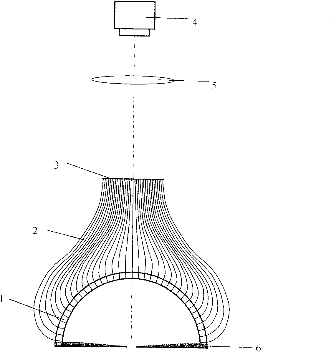
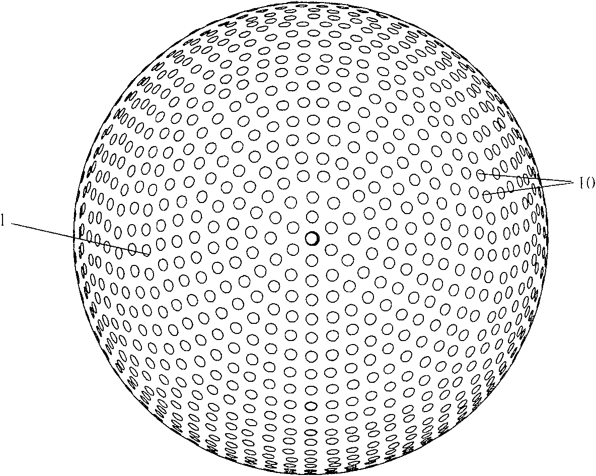
[0036] Embodiment 1: as figure 1The device for measuring the three-dimensional distribution of radiation light field includes a drilled hemispherical shell 1, an optical fiber 2, a drilled disk 3, an adjustable diaphragm 6 and an imaging system. All components are coaxially distributed along the main axis of the device, the adjustable diaphragm 6 is located at the bottom of the device, the drilled hemispherical shell 1 is located on the adjustable diaphragm 6, the lower surface of the adjustable diaphragm 6 coincides with the equatorial plane of the drilled hemispherical shell 1, And the center of the lower surface of the adjustable diaphragm 6 coincides with the center of the sphere of the drilled hemispherical shell 1 . The drilling disc 3 is located on the drilling hemispherical shell 1, and the two are connected by a number of optical fibers. The number of optical fibers is equal to the number of holes on the drilling hemispherical shell and the number of holes on the disc...
Embodiment 2
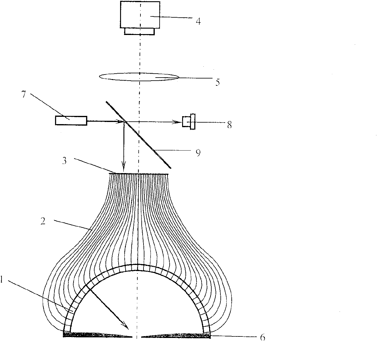
[0038] Embodiment 2: as figure 2 The device for measuring the three-dimensional distribution of the scattered light field on the surface of an object includes a drilled hemispherical shell 1, an optical fiber 2, a drilled disk 3, a light source power monitor 8, a beam splitter mirror 9, an adjustable diaphragm 6, a light source system and an imaging system . The structure of the device is based on the same structure as that of the device described in Embodiment 1, with the addition of a light source power monitor 8, a beam splitter 9 and a light source system. The beam splitter 9 is fixed between the disk 3 and the lens 5, and its normal line forms an angle of 45 degrees with the main axis of the device. Light source system 7 is made up of light source 18, lens 15, 17 and pinhole 16, and light source system 7 is positioned between disc 3 and lens 5, on the side of beam splitter 9, and its optical axis is perpendicular to the main axis of device, and light source system 7 As...
PUM
 Abstract
Description
Claims
Application Information
 - R&D
- Intellectual Property
- Life Sciences
- Materials
- Tech Scout
- Unparalleled Data Quality
- Higher Quality Content
- 60% Fewer Hallucinations
Browse by: Latest US Patents, China's latest patents, Technical Efficacy Thesaurus, Application Domain, Technology Topic, Popular Technical Reports.
© 2025 PatSnap. All rights reserved.Legal|Privacy policy|Modern Slavery Act Transparency Statement|Sitemap|About US| Contact US: help@patsnap.com


