Generation device of random polarization distributing vector light beam
A generation device, a technology of linearly polarized light, applied in optics, optical components, nonlinear optics, etc., can solve the problem of not being able to generate a variety of arbitrary polarization distribution vector beams at the same time, to reduce the impact of beam quality, and to achieve broad application prospects. Effect
- Summary
- Abstract
- Description
- Claims
- Application Information
AI Technical Summary
Problems solved by technology
Method used
Image
Examples
Embodiment 1
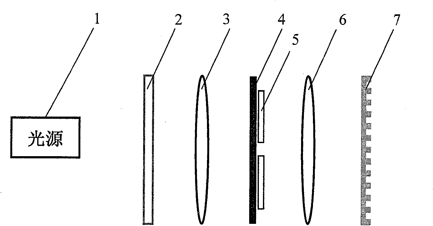
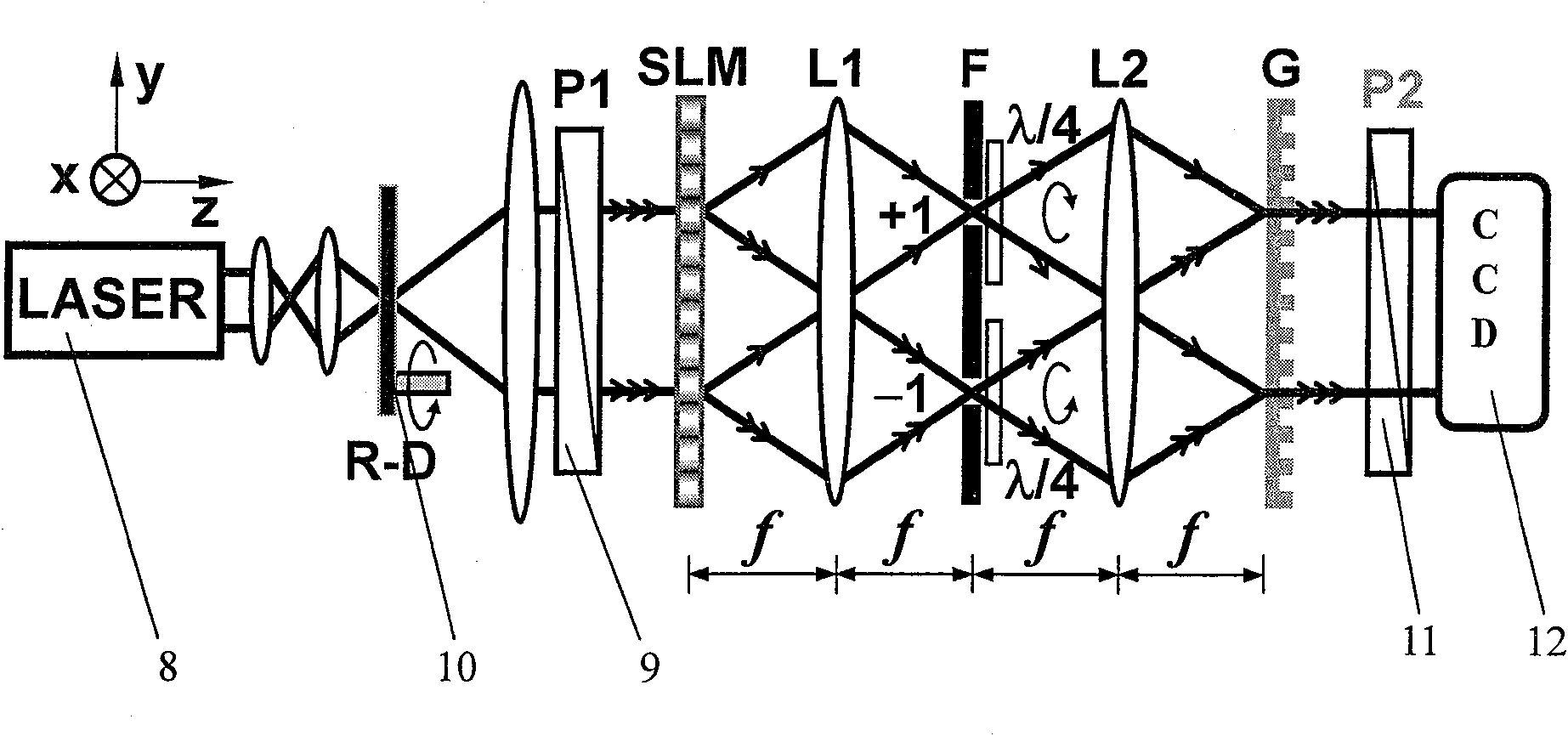
[0022] Such as figure 1 As shown, the core of the device for generating a vector beam with arbitrary polarization distribution according to the present invention is that a spatial light modulator 2, a first lens 3, and a filter 4 controlled by a computer are sequentially arranged along the light direction of the light source 1 that generates polarized light. , two quarter-wave plates 5, a second lens 6 and a phase-type Ronchi grating 7; the spatial light modulator 2 is located on the front focal plane of the first lens 3, and the filter 4 is set on the back focal plane of the first lens 3 The filter 4 is also located on the front focal plane of the second lens 6; the phase Ronchi grating 7 is located on the back focal plane of the second lens 6; two quarter-wave plates 5 are placed close to the backlight side of the filter 4. Such as figure 2 As shown, the complete optimal technical scheme of the generating device of the arbitrary polarization distribution vector light beam ...
Embodiment 2
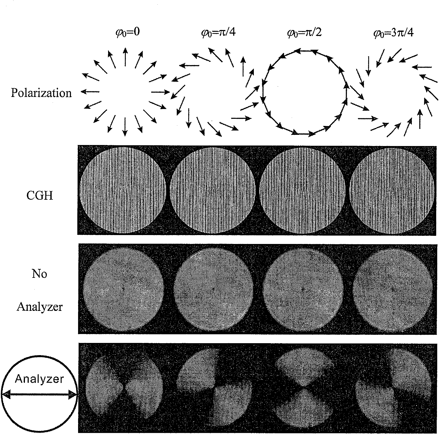
[0026] according to figure 1 The 4f optical system is built according to the principle, and the specific experimental system constructed based on this is as follows: figure 2 shown. Will image 3 The computational hologram (CGH) shown in column 2 in figure 2 in the CCD is obtained with the image 3 A cylindrically symmetric vector beam corresponding to the polarization distribution shown in the first column of . The beam intensities without linear polarizer 2 and with linear polarizer 2 inserted in front of the CCD are as follows image 3 As shown in columns 3 and 4 of , the dark spot at the center of the beam is caused by the singularity of the polarization state distribution uncertainty. When the linear polarizer 2 used as an analyzer is inserted in front of the CCD, there will be an extinction direction in the beam intensity distribution, and the extinction direction corresponds to In the four experimental results, the extinction direction is in the vertical direct...
Embodiment 3
[0028] according to figure 1 The 4f optical system is built according to the principle, and the specific experimental system constructed based on this is as follows: figure 2 shown. Will Figure 4 The computational hologram shown in column 2 in figure 2 The CCD is obtained with the Figure 4 The vector beam corresponding to the polarization distribution shown in the first column. The difference in the polarization state between the inner and outer modes leads to the appearance of a dark band at the boundary in the field intensity distribution, and the dark band gradually becomes clear with the increase of the polarization state difference between the inner and outer modes. Xiangshida's dark band is the clearest. Similar to Example 1, there is also the central singularity and the extinction direction after adding a linear polarizer. Here, the generation of m=1 dual-mode vector beams is realized by using our 4f system. Figure 4 Meaning of the symbols in: The experiment...
PUM
 Abstract
Description
Claims
Application Information
 - R&D
- Intellectual Property
- Life Sciences
- Materials
- Tech Scout
- Unparalleled Data Quality
- Higher Quality Content
- 60% Fewer Hallucinations
Browse by: Latest US Patents, China's latest patents, Technical Efficacy Thesaurus, Application Domain, Technology Topic, Popular Technical Reports.
© 2025 PatSnap. All rights reserved.Legal|Privacy policy|Modern Slavery Act Transparency Statement|Sitemap|About US| Contact US: help@patsnap.com


