Method for changing operation frequency of optical input device

A technology of input device and operating frequency, applied in the input/output process of data processing, instruments, electrical digital data processing, etc., can solve the problems of application limitations and high circuit complexity

Active Publication Date: 2010-05-12
PIXART IMAGING INC
View PDF5 Cites 0 Cited by
  • Summary
  • Abstract
  • Description
  • Claims
  • Application Information

AI Technical Summary

Problems solved by technology

However, since the optical input device needs to include related circuits to calculate the equivalent moving speed of the optical input device, the complexity of the circuit will be much higher, and the applicability of this method will be limited to a certain extent.

Method used


Image

  • Method for changing operation frequency of optical input device
  • Method for changing operation frequency of optical input device
  • Method for changing operation frequency of optical input device

Examples


Embodiment Construction

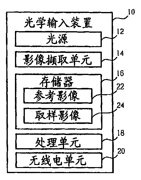
[0026] Please refer to figure 1 , figure 1 It is a block diagram of the optical input device 10 operating by adopting the method of changing the operating frequency of the optical input according to the replacement of the reference image of the present invention. The optical input device 10 includes a light source 12 for generating light, an image capture unit 14 for capturing images, a memory 16 for storing images 22, 24 captured by the image capture unit 14, and a processing unit 18 for to analyze the images 22 , 24 captured by the image capture unit 14 , and a radio unit 20 is used to output pointer signals generated by the processing unit 18 after analyzing the images 22 , 24 in a radio transmission manner.

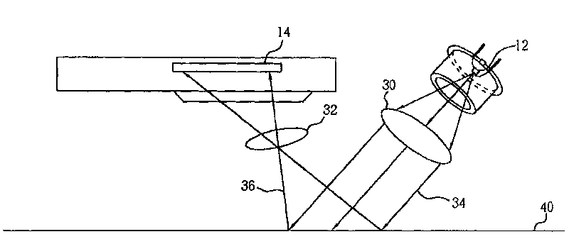
[0027] Please refer to figure 2 , figure 2 for figure 1 A schematic diagram of the light source 12 and the image capture unit 14. A first lens 30 and a second lens 32 are arranged between the light source 12 and the image capture unit 14, wherein the light 34 em...


PUM


Abstract

A method for varying operation frequency of optical input device includes utilizing a reference image to analyze multiple sampling image in order to judge movement of said optical input device and varying operation frequency of said optical input device according to used time length of reference image.

Description

technical field [0001] The invention relates to a method for controlling an optical input device, in particular to a method for changing the operating frequency of the optical input device according to the replacement of a reference image. Background technique [0002] In recent years, optical input devices (such as optical mice) have been used by more and more consumers due to their precise sensitivity and ease of use. In addition, with the maturity of the wireless transmission technology, the optical input device gradually adopts the wireless transmission technology for data transmission. Usually, the wireless optical input device is powered by a battery, but the battery needs to be replaced or recharged every once in a while for a device powered by a battery. Therefore, how to avoid the energy consumption of the wireless optical input device has become one of the important issues. [0003] In order to save energy consumption of the wireless optical input device, US Pate...

Claims


Application Information

Patent Timeline
Patent Type & Authority Patents(China)
IPC IPC(8): G06F3/038
Inventor 林俊煌
Owner PIXART IMAGING INC
Why Eureka
Try Eureka