Vacuum ejector pumps

A technology for vacuum jet pumps and nozzles, which is applied to jet pumps, pumps, non-displacement pumps, etc., and can solve problems such as fracture or deformation

Inactive Publication Date: 2007-07-18
KOREA PNEUMATIC SYST CO LTD
View PDF1 Cites 14 Cited by
  • Summary
  • Abstract
  • Description
  • Claims
  • Application Information

AI Technical Summary

Problems solved by technology

[0007] However, a problem with the conventional vacuum pump 200 is that the joints between the nozzles 202, 203, 204, and 205 are prone to breakage or deformation (bending or twisting) under external pressure or impact when the vacuum pump 200 is in use.
In addition, when the vacuum pump 200 breaks, all parts of the pump must be disassembled to check the vacuum pump 200

Method used


Image

  • Vacuum ejector pumps
  • Vacuum ejector pumps
  • Vacuum ejector pumps

Examples


Embodiment Construction

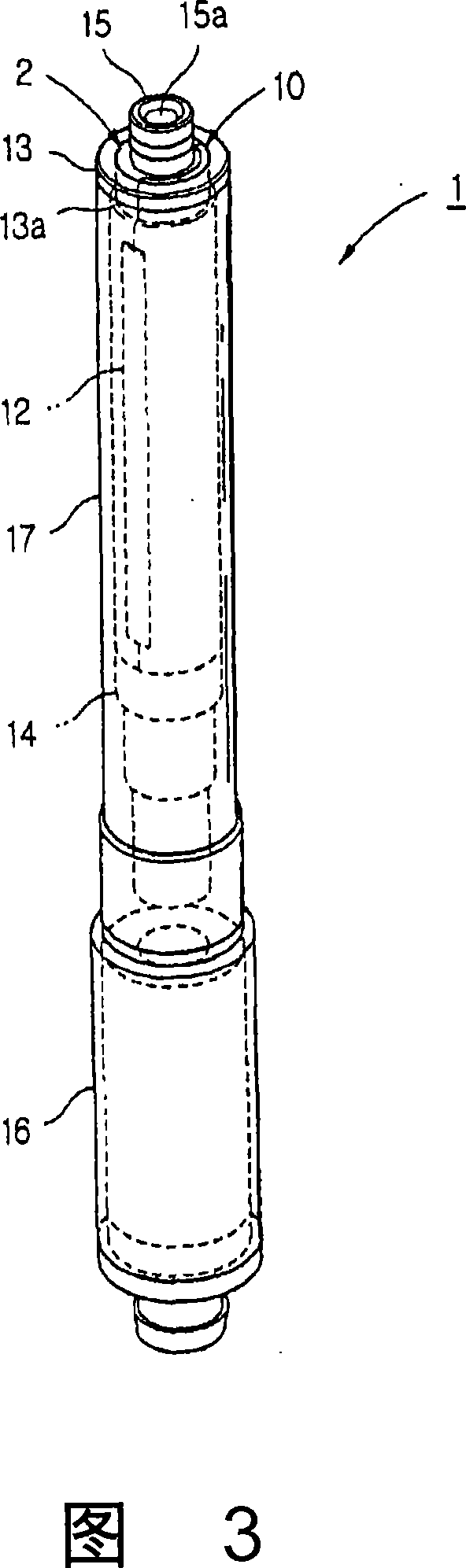
[0022] As shown in FIGS. 3 to 9, a vacuum ejector pump according to the present invention is indicated by reference numeral 1 . The jet vacuum pump 1 comprises a cylindrical nozzle body 2 , a cover 10 and fastening devices 13 and 14 . An opening 3 is provided at a predetermined position of the nozzle body 2 . A cover 10 is provided to cover the opening 3 of the nozzle body 2 . Fastening means 13 and 14 serve to fasten the nozzle body 2 to the cover 10 .

[0023] One or more mounting nozzles 4 and 5 are arranged in the nozzle body 2 and are visible through the opening 3 . The mounting nozzles 4 and 5 are arranged coaxially with the nozzle body 2 and are mounted through partition walls 6 and 7 provided in the nozzle body 2 so as to be integral with the nozzle body 2 (as shown). The mounting nozzles 4 and 5 may comprise a plurality of nozzles, so that the ejector vacuum pump 1 is characterized by the required efficiency. In this case, the installation nozzles 4 and 5 are arra...


PUM


Abstract

Disclosed herein is a vacuum ejector pump operated by compressed air which flows in and out at high velocity, thus creating negative pressure in an outer surrounding space (S). The vacuum ejector pump includes a cylindrical nozzle body (2) and a cover (10). The nozzle body has at a predetermined position thereof an opening (3). One or more mounting nozzles (4, 5) are coaxially installed in the nozzle body and are visible through the opening (3). Holes (8) are formed in the wall of the nozzle body to allow the pump to communicate with the surrounding space (S). The cover functions to cover the opening of the nozzle body. Further, the pump includes flexible valve members (9) to open or close the holes, and fastening means (13, 14) to fasten the nozzle body to the cover.

Description

technical field [0001] The present invention relates generally to vacuum jet pumps which are operated by high velocity inflow and outflow of compressed air, thereby creating a negative pressure in a space, and in particular to a vacuum jet pump comprising a jet having one or more A cylindrical nozzle body to which the nozzle is mounted, and a cap mounted on the nozzle body so as to cover an opening formed at a predetermined position of the nozzle body. Background technique [0002] A conventional vacuum pump called a multi-stage ejector is shown in Figure 1. The vacuum pump 100 includes chambers 101 , 102 and 103 arranged in series, and a plurality of nozzles 105 , 106 and 107 installed through partition walls between the chambers 101 , 102 and 103 . Chambers 101 , 102 and 103 communicate with a common vacuum chamber 104 through holes 108 , 109 and 110 . The vacuum pump 100 is connected to an external device (for example, a suction device) through a port 111 formed at a pr...

Claims


Application Information

Patent Timeline
Patent Type & Authority Applications(China)
IPC IPC(8): F04F5/22F04F5/46F04F5/52
CPCF04F5/52F04F5/467F04F5/22
Inventor 赵镐英
Owner KOREA PNEUMATIC SYST CO LTD
Why Eureka
Try Eureka