Supersonic wave checking device

An inspection device and ultrasound technology, which is applied in sonic diagnosis, infrasonic diagnosis, ultrasonic/sonic/infrasonic diagnosis, etc. It can solve problems such as deterioration of image quality, breast deformation, and inability to realize popularization of practical devices, etc.

Inactive Publication Date: 2007-07-25
KK TOSHIBA +1
View PDF3 Cites 36 Cited by
  • Summary
  • Abstract
  • Description
  • Claims
  • Application Information

AI Technical Summary

Problems solved by technology

[0009] As described above, various proposals have been made as ultrasonic examination devices that can be used for breast cancer diagnosis, but there are problems in examination time, breast deformation, image quality deterioration due to multiple reflections, complicated drive mechanism, water pollution, excessive There are many problems such as the display method of the tomographic image, and none of the proposals can be widely used as a practical device in the existing examples.

Method used


Image

  • Supersonic wave checking device
  • Supersonic wave checking device
  • Supersonic wave checking device

Examples


no. 1 Embodiment approach

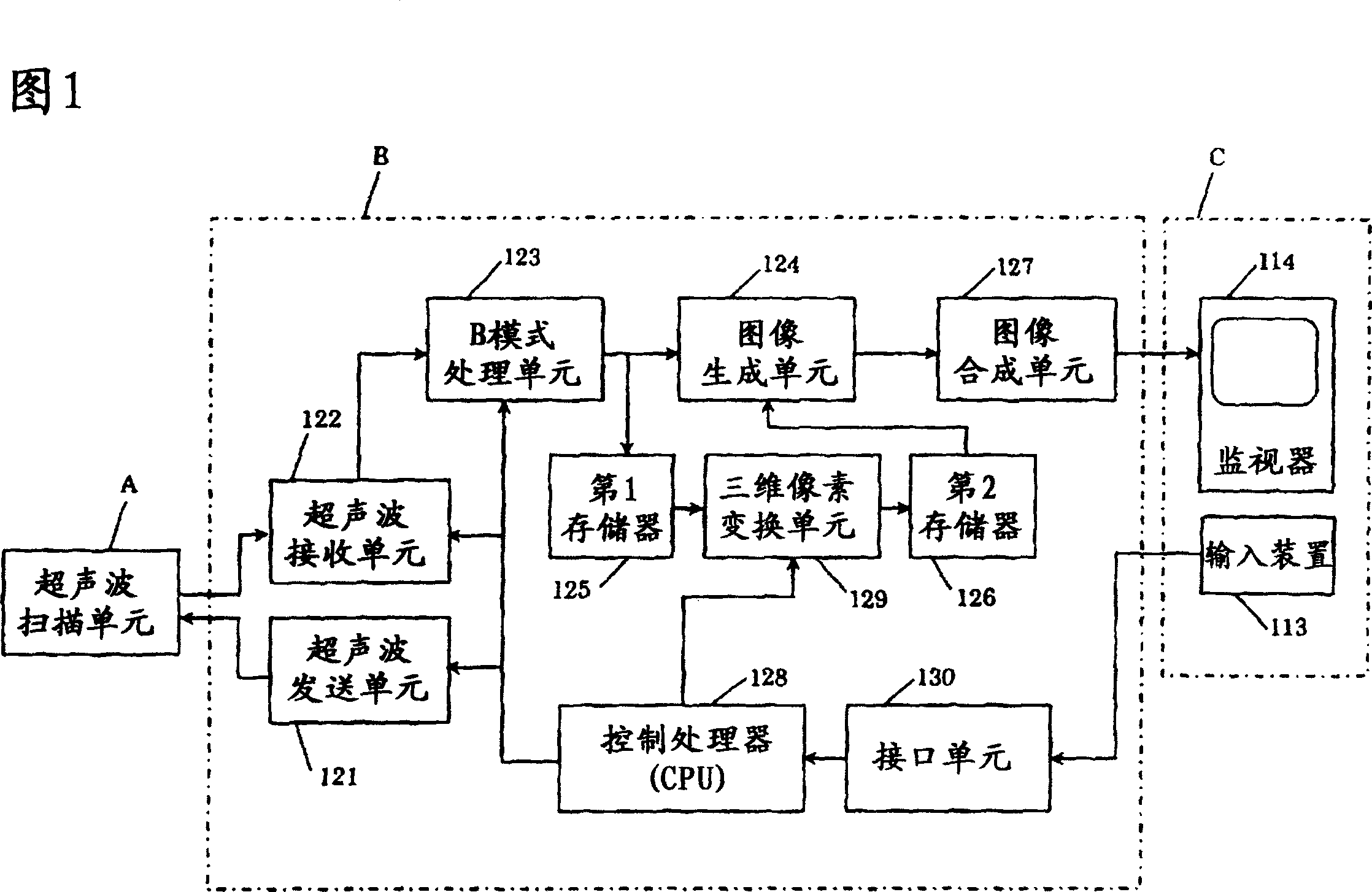
[0035]FIG. 1 is a block configuration diagram of an ultrasonic inspection apparatus according to an embodiment of the present invention. As shown in FIG. 1 , this ultrasonic inspection apparatus includes an ultrasonic scanning unit A, an apparatus body B, and a console C. As shown in FIG. The device body B is provided with an ultrasonic transmitting unit 121, an ultrasonic receiving unit 122, a B-mode processing unit 123, an image generating unit 124, a first memory 125, a second memory 126, an image synthesis unit 127, a control processor (CPU) 128, a voxel Transformation unit 129 , interface unit 130 . In addition, the console C includes an input device 113 and a monitor 114 . In the following images, the functions of each component are explained.

[0036] The ultrasonic scanning unit A includes an ultrasonic array probe, a rotation mechanism for rotating the ultrasonic array probe while the ultrasonic transmitting and receiving surface faces the subject, a liquid containe...

Embodiment 1

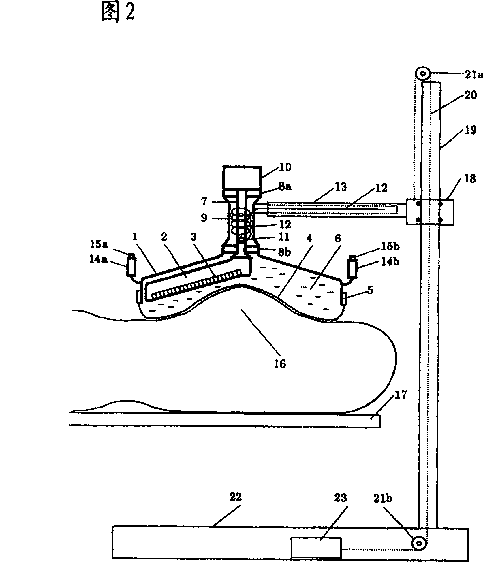
[0050] FIG. 2 is a diagram showing an ultrasonic scanning unit A according to the first embodiment. The sealed liquid container filled with warm water 6 is composed of a support cover 1 , an ultrasonic transmission membrane 4 , and a membrane fixing unit 5 , and the ultrasonic array probe 2 is placed in the warm water 6 . The liquid container may be sealed or not. The ultrasonic array probe 2 is fixed to the rotating shaft 7 at a predetermined angle, the rotating shaft 7 is supported by the bearings 8a and 8b, and the rotating shaft 7 is rotated by the motor 10, so that the ultrasonic array probe rotates in the liquid. The bearings 8a, 8b are fixed on the outer cylinder 9, and the outer cylinder 9 is further fixed on the front end of the telescopic support arm 13. The other end of the support arm 13 is coupled to a support 19 through a coupling unit 18 . The pillar 19 is fixed on the pillar stand 22 . Usually, warm water is used as the liquid, and the warm water is circulat...

Embodiment 2

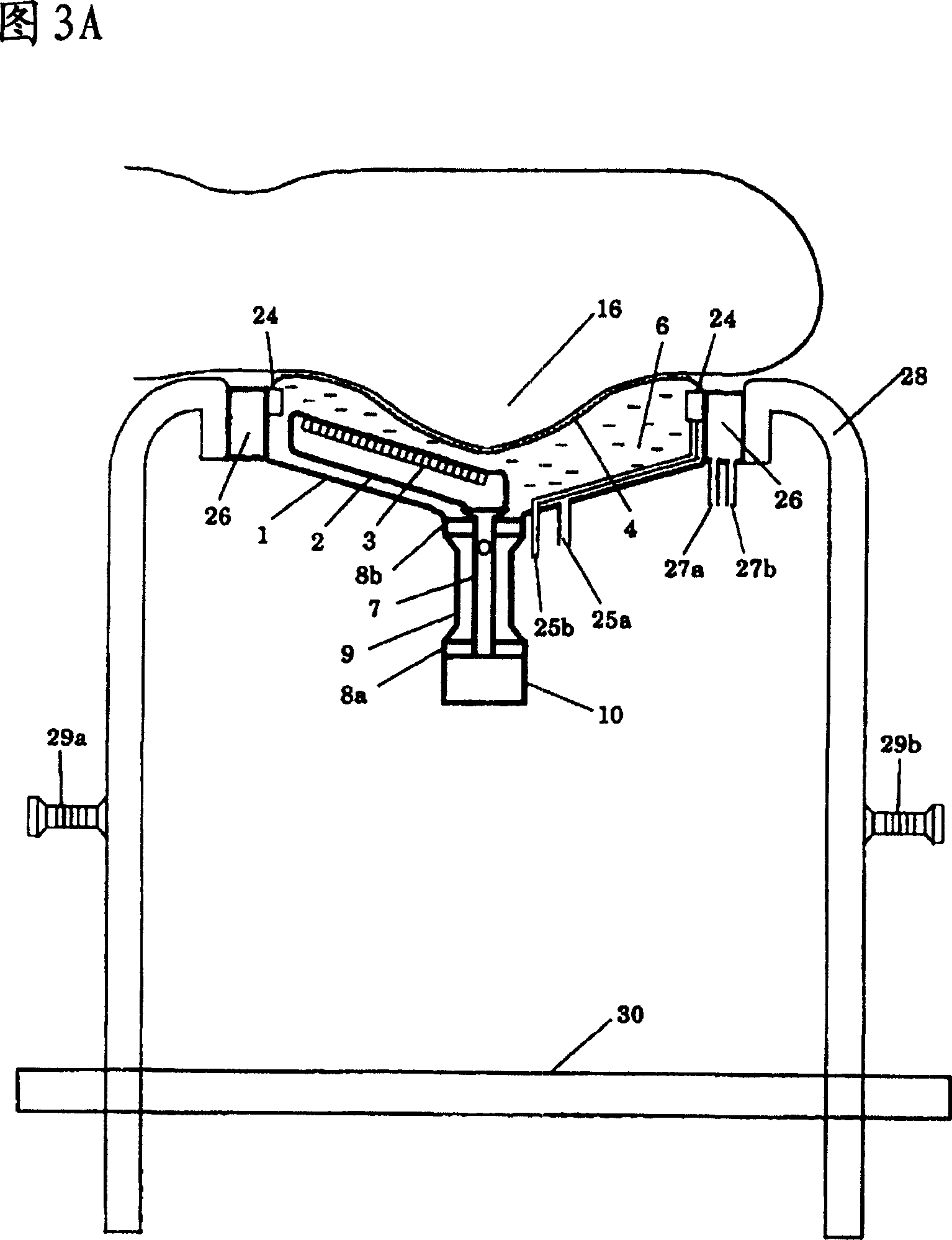
[0056] FIG. 3A is a diagram showing an ultrasonic scanning unit A related to the second embodiment. It is basically the same as FIG. 2 , but the liquid container is sealed upside down, and the side of the support cover 1 is fixed to the outer frame 28 via the water supply and drainage groove 26 . In FIG. 3A, conduits 25a and 25b for circulating warm water at a constant temperature of about 37 degrees in a liquid container omitted in FIG. 2 are shown. Warm water at a constant temperature flows in from the inflow conduit 25a, passes through the container, and then flows out from the water outlet 24 through the outflow conduit 25b to circulate. The water outlet 24 is located on the upper portion of the enclosed liquid container, and even if air bubbles are mixed in the enclosed liquid container, the warm water can be discharged from the water outlet 24 following the flow of the warm water.

[0057]Another difference between the system related to the second embodiment and the sys...


PUM


Abstract

The invention provides an ultrasonic inspection device which can simplify the mechanical constitution by fixing the ultrasonic array probe to a rotating shaft in a predetermined degree, and electrically controls the ultrasonic beam in a manner that the ultrasonic transmitting and receiving direction is approximately vertical to the breast surface, and collects the data of the entire region containing C' section of the breast only by turning the probe. In addition, the membrane between the probe and the breast has a reticulation constitution thereby reducing multiple reflections. Further, the invention can get correct diagnosis in short time by displaying B mode image and C mode image simultaneously.

Description

technical field [0001] The present invention relates to an ultrasonic examination apparatus for diagnosing breast diseases, and more particularly to an ultrasonic breast examination apparatus that can also be used for examination and diagnosis of breast cancer. Background technique [0002] In my country, the prevalence of breast cancer is the highest between the ages of 45 and 50. Since 2004, breast cancer examination and diagnosis by observation and touch diagnosis alone have been abolished, and breast cancer examination and diagnosis by mammography has been carried out since the age of 40 (please refer to 2004 Japanese Ministry of Health, Labor and Welfare, Elderly Health Division Changfa No. 0427001). However, since the contrast of the X-ray image of the soft tissue of the living body without using a contrast agent is extremely weak except for the detection of tiny calcifications that greatly attenuate X-rays, it has been pointed out that there is a high possibility of om...

Claims


Application Information

Patent Timeline
Patent Type & Authority Applications(China)
IPC IPC(8): A61B8/00
CPCA61B8/406A61B8/14A61B8/463A61B8/4218A61B8/0825A61B8/4281A61B8/4209
Inventor 饭沼一浩濑尾育弍
Owner KK TOSHIBA
Why Eureka
Try Eureka