

Method for controlling band shape of thin band continuously casting
A control method and thin strip technology, which is applied in the field of strip shape control in thin strip continuous casting, can solve problems such as the influence of uniform solidification of the cast strip, the inability to ensure consistent cooling performance, and the complex structure of crystallization rolls, etc., and achieve a reasonable strip shape control method Simple, easy to control, low dependence on external conditions
- Summary
- Abstract
- Description
- Claims
- Application Information
AI Technical Summary
Problems solved by technology
Method used
Image

Examples
Embodiment 1
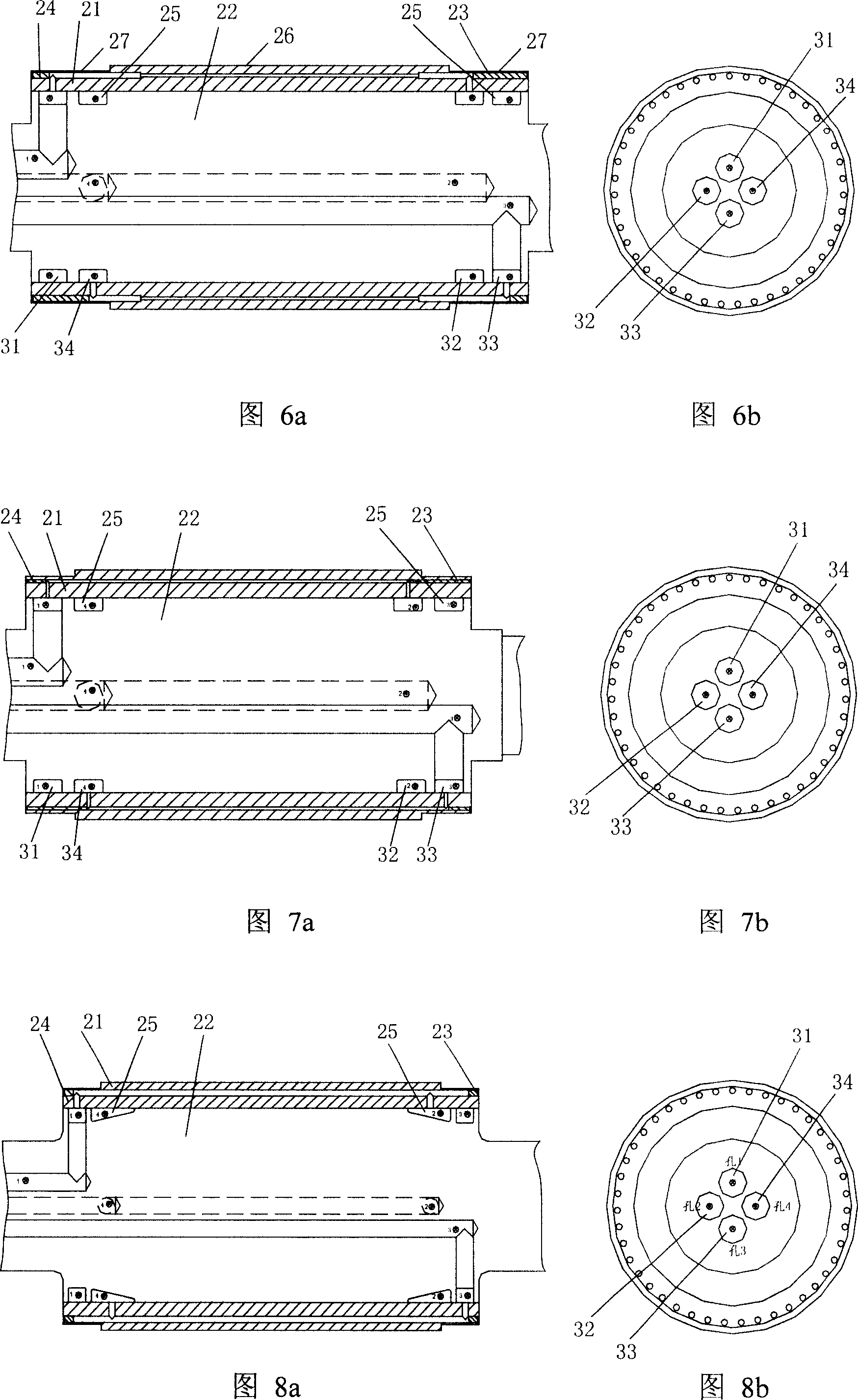
[0030] Referring to Fig. 6a and Fig. 6b, the crystallization roller is composed of a roller shaft 22, a roller sleeve 21 fixed thereon, and a plug 23 and a plug 24 for sealing the cooling water channel. The cooling water flows in opposite directions along the axial direction of the crystallization roll in the hole-shaped channel in the roll sleeve 21, and the diameter of the water hole near the edge of the crystallization roll and the molten steel contact area 26 is larger than that in the middle, and the increase ratio depends on the thickness of the casting strip. determined, the experience value is R=1.25R 0 , R 0 R is the diameter of the water hole in the middle, and R is the diameter of the water hole in the edge. During the casting operation, more heat will be taken away from the edge of the crystallization roll, and the cooling speed will be faster, so the strip steel will be thinner at this position. In addition, in order to avoid the water tank 25 entering and leavi...
Embodiment 2
[0032] Referring to Fig. 7a and Fig. 7b, the crystallization roller is also composed of a roller shaft 22, a roller sleeve 21 fixed thereon, and a plug 23 and a plug 24 for sealing the cooling water channel. Cooling water flows in opposite directions along the axial direction of the crystallization rolls in the hole-shaped channel in the roll sleeve 21, and the water inlet groove 25 is close to the edge of the crystallization rolls. During the casting operation, the cooling speed of the edge of the crystallization rolls is fast, and the strip steel will be relatively thin at this position. Compared with the structure shown in Figure 6, the crystallization roller has a relatively compact structure, and the cooling effect of the crystallization roller is more ideal after reaching thermal equilibrium.
Embodiment 3
[0034] Referring to Fig. 8a and Fig. 8b, the crystallization roller shown in Fig. 8 changes the water inlet groove 25 into an irregular trapezoidal shape on the basis of Fig. 7, so that the actual application cooling area of the enlarged crystallization roller side is gradually increased, The cooling intensity changes slowly, which can make the transition of different heat fluxes on the surface of the crystallization roller smooth, and avoid the occurrence of cracks in the casting belt caused by a large temperature gradient.
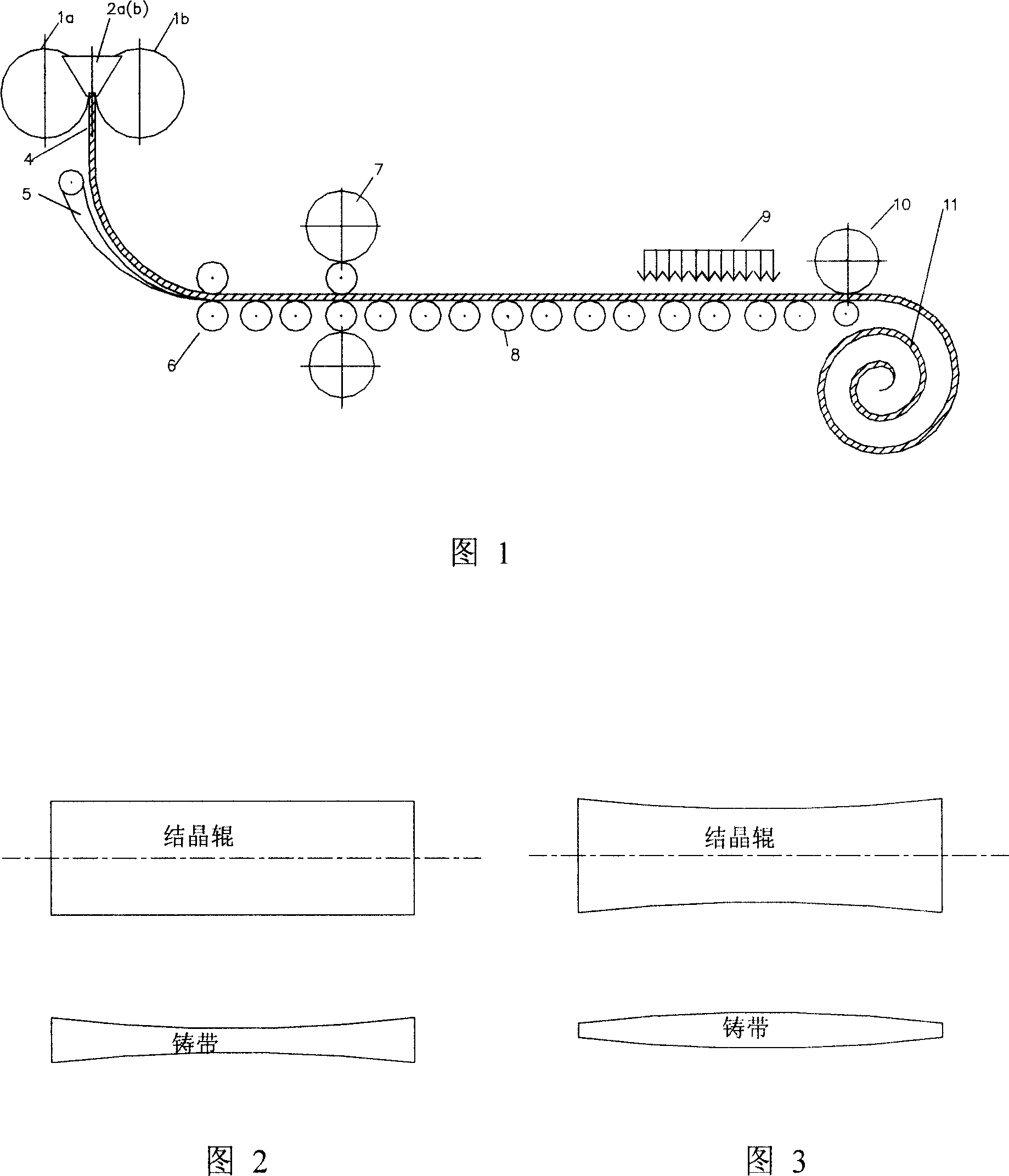
[0035] The invention is suitable for casting a metal casting strip with a thickness of 1.5-5mm by using a twin-roller thin strip continuous casting machine.
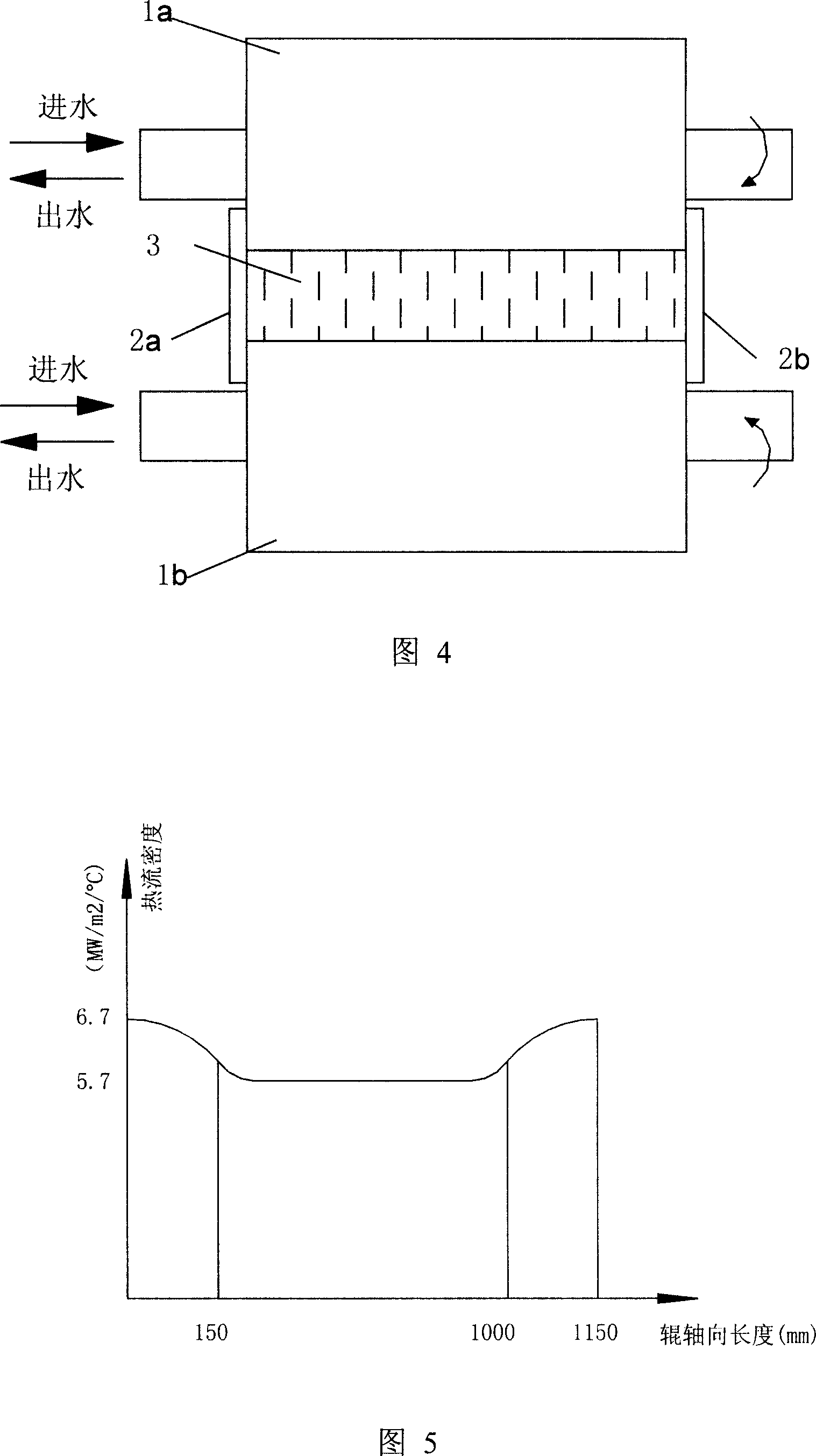
[0036] The invention increases the cooling strength of the cooling water from both sides of the crystallization roll, changes the heat flux density of the local roll surface of the crystallization roll, improves the quality of the thin strip continuous casting edge, makes the cast strip flat along...
PUM
 Abstract
Description
Claims
Application Information