Composition type lock in use for safe deposit box

A combination and safe technology, applied in the field of lock structure, can solve problems such as troublesome storage, battery exhaustion, and component failure, and achieve the effect of avoiding the use of keys, beautiful panel layout, and improving security

Inactive Publication Date: 2007-07-25
苏州孔雀信天游电子有限公司
View PDF1 Cites 4 Cited by
  • Summary
  • Abstract
  • Description
  • Claims
  • Application Information

AI Technical Summary

Problems solved by technology

[0003] Among the various electronic locks mentioned above, due to the use of electronic components and power supplies, there must be failures and problems such as component failure, damage, and battery exhaustion. Therefore, electronic locks driven by electricity must be equipped with emergency door locks. In the technology, locks with keys are usually used as emergency door locks, such as the "Electromechanical Blade Lock" (CN1125226C) published by the Chinese Invention Patent. The security of the lock is higher than that of ordinary marble locks, but the key is still needed to open it, and there are problems such as easy loss or imitation of the key, and there are certain troubles in storage, which reduces the confidentiality and reliability of the safe; At the same time, blade locks and marbles are used as emergency door locks, and both have the possibility of being opened by technology, thereby reducing the safety of the safe

Method used


Image

  • Composition type lock in use for safe deposit box
  • Composition type lock in use for safe deposit box
  • Composition type lock in use for safe deposit box

Examples


Embodiment 1

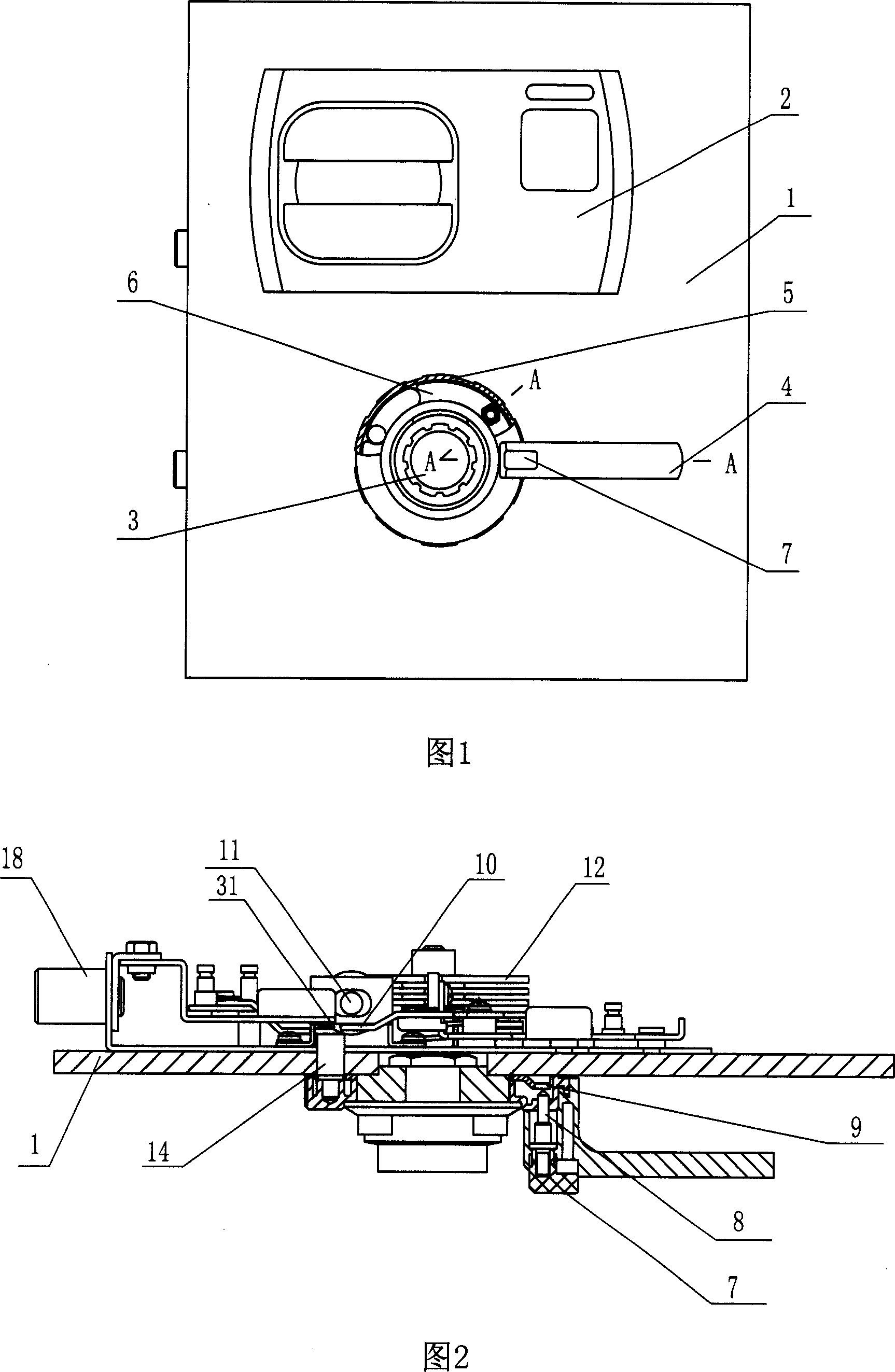
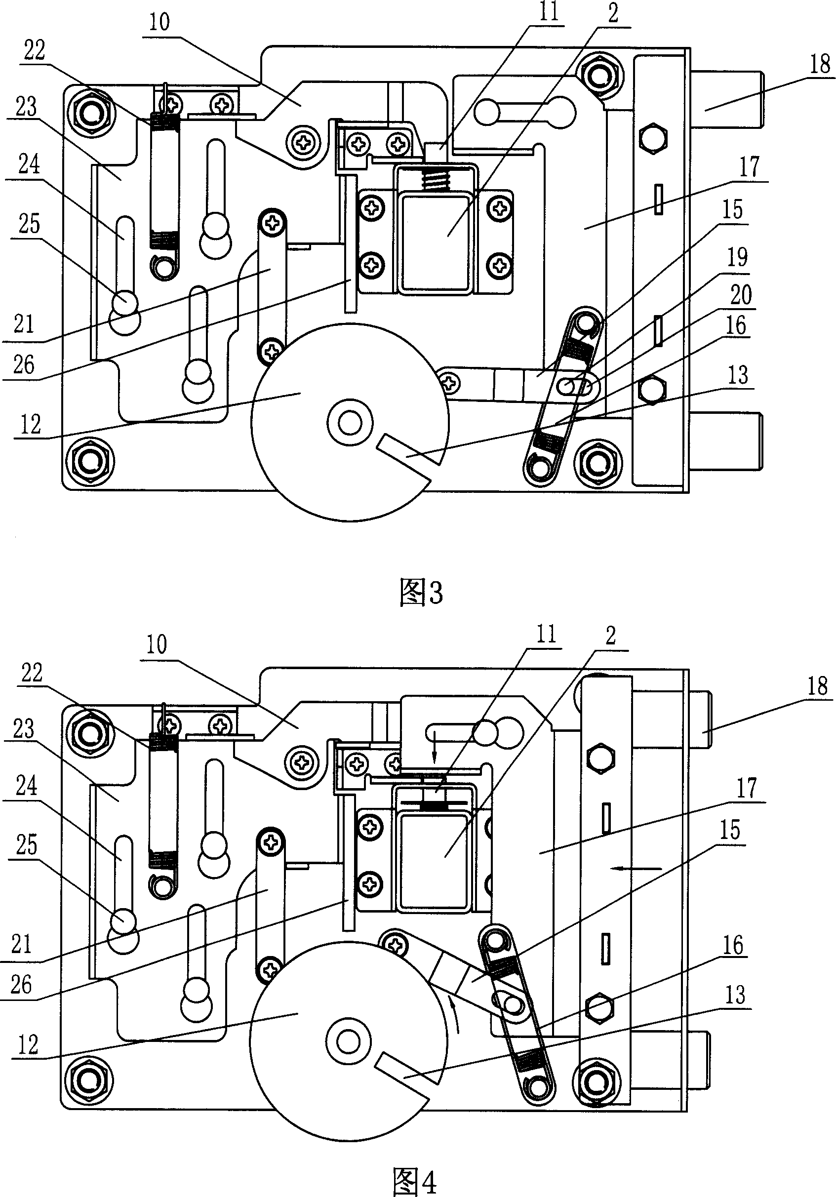
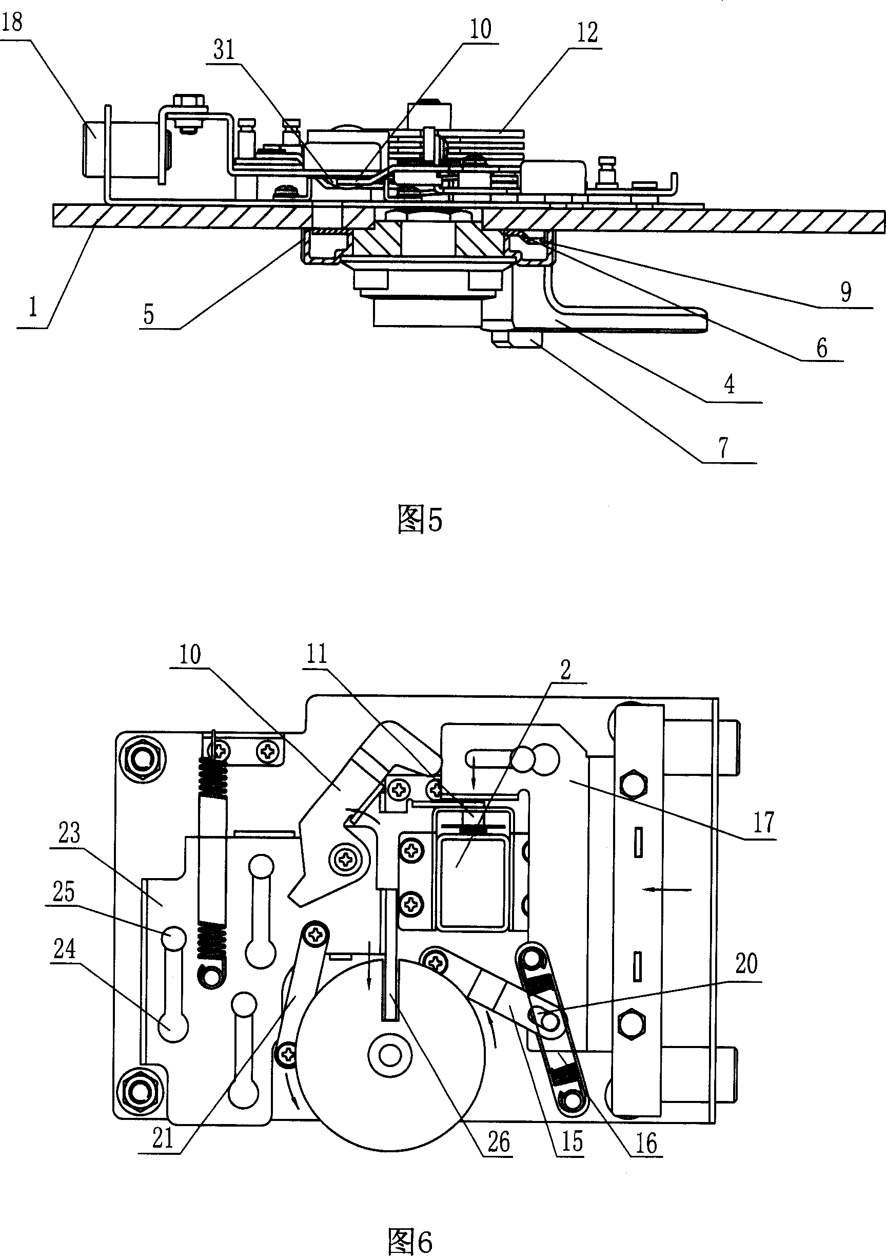
[0030] Embodiment 1: Referring to accompanying drawings 1 to 6, a combined lock for a safe includes a panel 1, a fingerprint electronic lock 2 installed on the panel, a turntable combination lock 3 and a transmission mechanism and a lock. The handle 4 connected by the bolt structure, the handle is provided with inner and outer drive rings, and the inner and outer drive rings are sleeved on the outside of the turntable of the rotary dial type combination lock, and the outer drive ring 5 is sleeved on the outside of the inner drive ring 6. The latter is driven in parallel through a clutch mechanism, which includes a drive button 7, a clutch pin 8 and a return spring sleeved outside the clutch pin. The handle 4 is provided with a groove for the drive button, and the clutch pin is located at the button action end. It is located in the sliding channel that runs through the outer drive ring 8, and cooperates with the pin hole opened on the inner drive ring to form a parallel connecti...

Embodiment 2

[0033] Embodiment 2: Referring to accompanying drawings 6 to 8, a combined lock for a safe includes a panel 1, a fingerprint electronic lock 2 installed on the panel, a turntable combination lock 3 and a transmission mechanism and a lock. The handle 4 connected by the bolt structure, the handle is provided with inner and outer drive rings, and the inner and outer drive rings are sleeved on the outside of the turntable of the turntable combination lock, and the outer drive ring 5 is sleeved on the outside of the inner drive ring 6. Parallel transmission through a clutch mechanism, the clutch mechanism is that the end of the handle 4 is rotatably connected with the outer drive ring through a bump 27, and the active end of the bump 27 is provided with a clutch pin 8 that runs through the outer drive ring 5, The outer cover of clutch pin 8 is provided with a return spring, and the inner drive ring at the clutch pin place has a pin hole 9 matching it; the output end of the outer dri...


PUM


Abstract

The present invention relates to a combined lock for strongbox. It includes the following several portions: panel, electronic lock mechanical lock, lock bolt driving mechanism and handle connected with lock bolt structure by means of lock bolt driving mechanism. The described mechanical lock is a figure plate type cipher code lock. Said invention also provides the working principle of said combined lock for strongbox and its operation method. It can effectively raise safety coefficient of strongbox.

Description

technical field [0001] The invention relates to a lock structure, in particular to a combined lock for a safe. Background technique [0002] At present, the unlocking methods of safes and safe deposit box series products manufactured by the safe industry are divided into two categories: electronic and mechanical. Electronics include fingerprints, passwords, and magnetic cards, and mechanical ones include keys and rotary passwords. The electronic opening method is to input the correct unlocking signal (such as fingerprint, password or magnetic card, etc.), the safety device (including electromagnet and motor) is energized to drive the valve tongue to shrink, and the door is opened by turning the handle to pull the lock bolt; mechanical opening The way is to pull the lock bolt to open the door by turning the lock cylinder (insert the key matching the lock cylinder or turn the dial according to the correct password to make the blade password slots consistent). [0003] Among ...

Claims


Application Information

Patent Timeline
IPC IPC(8): E05B65/52E05B63/14E05B49/00E05B37/20
Inventor 倪苏平徐再颖卢伟
Owner 苏州孔雀信天游电子有限公司
Why Eureka
Try Eureka