System of monitoring road traffic

A monitoring system and road traffic technology, applied in the field of monitoring systems, can solve the problems that the vehicle speed information cannot truly reflect the driving situation of the vehicle, increase the workload of installing equipment, etc., and achieve the effect of great practical value, low price and high reliability

Inactive Publication Date: 2007-07-25
DALIAN CHANGFU RUIHUA GRP CO LTD
View PDF0 Cites 35 Cited by
  • Summary
  • Abstract
  • Description
  • Claims
  • Application Information

AI Technical Summary

Problems solved by technology

On the one hand, this will cause each detector to have a wire connected to the controller to transmit its own measurement signal, which will undoubtedly increase the workload of installing the equipment; on the other hand, it will also limit the installation position of the detector, because These common

Method used


Image

  • System of monitoring road traffic
  • System of monitoring road traffic
  • System of monitoring road traffic

Examples


Embodiment Construction

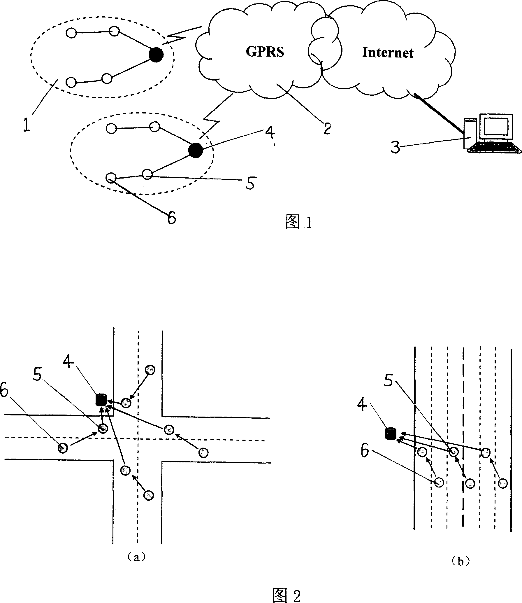
[0022] The road traffic monitoring system shown in Figure 1 is composed of a control center 3, a wireless communication module 2 and an information collection system 1. The information collection system is composed of a wireless sensor node and a control node 4. The wireless sensor node is installed on the lane to measure traffic Traffic, driving speed and other information are collected, and the information is transmitted to the control node. The control node and the one-hop and two-hop wireless sensor nodes distributed in an area are organized into a two-hop star network, as shown in Figure 2, Figure 2 (a) is measuring flow data in various directions at an intersection such as measuring at an intersection. Figure 2(b) measures the traffic flow, driving speed and other data of each lane on the road away from the intersection. The control node obtains information from the wireless sensor node network on the one hand, and sends the information to the control center through the ...


PUM


Abstract

A monitoring system of road traffic is prepared for erecting radio transducer on lanes to measure traffic flow rate and driving speed and to transmit measured information to control node, organized control node and radio transducer distributed at a region to be a multi-jump star type of network being used to obtain information from radio transducer node network on one hand and on the other hand to send obtained information to control center through GPRS communication module.

Description

Technical field: [0001] The present invention relates to monitoring systems, especially traffic monitoring systems. Background technique: [0002] With the continuous increase of car ownership, urban road congestion is becoming more and more serious. In order to effectively guide urban traffic, the traffic management department must grasp the current driving conditions of urban roads in a timely manner, and the traffic information collection system is the key link to complete this task. There are many types of traffic information collection systems. At present, the most widely used in urban streets are induction coil detectors, ultrasonic detectors and video detectors. A common feature of these commonly used detection devices is that they do not cooperate with each other and complete their own tasks independently. For example, each induction loop detector is an independent unit, which is responsible for detecting vehicles passing through it, and has no relationship with ot...

Claims


Application Information

Patent Timeline
IPC IPC(8): G08G1/01G08G1/052G08G1/065G08G1/042H04Q7/20
Inventor 王莹李世宽
Owner DALIAN CHANGFU RUIHUA GRP CO LTD
Why Eureka
Try Eureka