Electric energy transmitting device with a phase conductor and an screen conductor

A technology for power transmission and shielded conductors, applied in fully enclosed busbar devices, cable installation, gas-filled/oil-filled cable accessories, etc., can solve problems affecting load flow and achieve the effect of stabilizing the external profile

Inactive Publication Date: 2007-07-25
SIEMENS AG
View PDF1 Cites 2 Cited by
  • Summary
  • Abstract
  • Description
  • Claims
  • Application Information

AI Technical Summary

Problems solved by technology

Gas-insulated electrical conductors, when integrated into an existing network of electrical energy transmission conductors, can influence the load flow in an undesired manner due to their extremely low resistance

Method used


Image

  • Electric energy transmitting device with a phase conductor and an screen conductor
  • Electric energy transmitting device with a phase conductor and an screen conductor
  • Electric energy transmitting device with a phase conductor and an screen conductor

Examples


Embodiment Construction

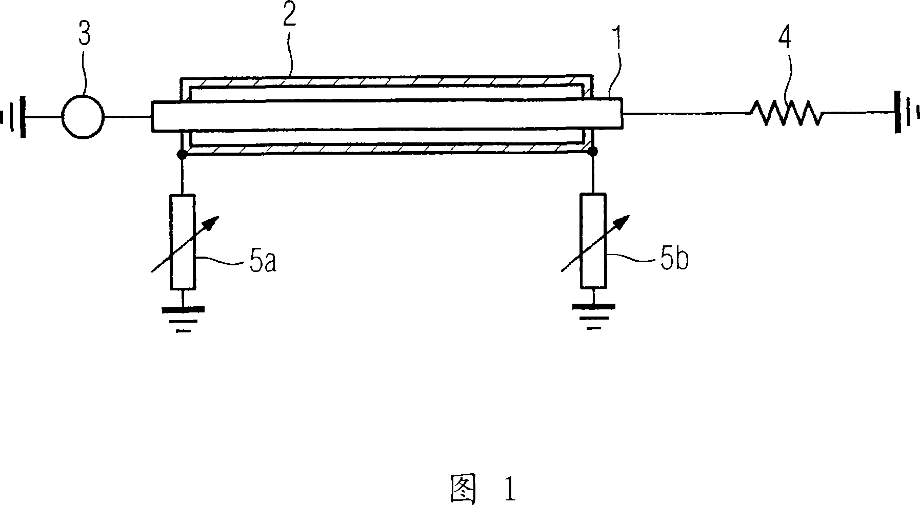
[0028] FIG. 1 schematically shows a gas-insulated conductor in a cross-sectional view. The gas-insulated line has a phase conductor 1 and a shield conductor 2 . The shield conductor 2 surrounds the phase conductor 1 . The phase conductor 1 is connected at the input to a feeding power grid 3 . The phase conductor 1 is connected at the output to an electrical consumer 4 . The energy flow can be conveyed from the power grid 3 to the consumer 4 via the phase conductor 1 . The shield conductor 2 of the gas-insulated electrical line is grounded both at the input and output. This grounding is effected via a component 5a, 5b with variable impedance, respectively. The component can have the characteristics of resistance, capacitance or inductance according to different needs. In addition, electronic components may be included in the components 5a, 5b. By adjusting the impedance of the components 5a, 5b with variable impedance, it is possible to induce stronger or weaker reverse c...


PUM


Abstract

An electric energy transmitting device comprises a phase conductor (1, 1a, 1b, 1c). The phase conductors (1, 1a, 1b, 1c) are each surrounded by an external conductor (2, 2a, 2b, 2c). The external conductors (2, 2a, 2b, 2c) are subdivided into sections (2a', 2a'', 2b', 2b'', 2c', 2c''). The individual sections (2a', 2a'', 2b', 2b'', 2c', 2c'') can be electrically connected by inserting a module with variable impedances (6a, 6b, 6c). A grounding of individual sections of the external conductor (2) ensues via a module with a variable impedance (6e, 6f, 6g, 6h, 6i, 6j, 5a, 5b).

Description

technical field [0001] The invention relates to an electric energy transmission device with a phase conductor and a shielding conductor, wherein the phase conductor is used for the transmission of electric energy flow. Background technique [0002] Such an electrical energy transmission device is disclosed, for example, by the patent document US 5,530,200. The electrical energy transmission means there are designed as gas-insulated electrical conductors. The phase conductors are surrounded by shielding conductors designed to be gas-tight. The interior of the shield conductor is filled with insulating gas under elevated pressure. Such gas-insulated electrical conductors have a very low resistance due to their structural design. Within the interwoven network of power-transmitting conductors, a specific distribution of the load flow or energy flow is controlled by means of the conductor impedance. Gas-insulated electrical conductors, when integrated into an existing network...

Claims


Application Information

Patent Timeline
Patent Type & Authority Applications(China)
IPC IPC(8): H02G5/06H02G15/105
CPCH02G15/24
Inventor 冈瑟·舍夫纳
Owner SIEMENS AG
Why Eureka
Try Eureka