Display device and display panel driver using grayscale voltages which correspond to grayscales

A grayscale voltage and display device technology, applied to static indicators, instruments, and conversion equipment without intermediate conversion to AC, etc., can solve problems such as image quality degradation, and achieve the effect of improving quality and stabilizing grayscale voltage

Inactive Publication Date: 2011-02-16
RENESAS ELECTRONICS CORP
View PDF15 Cites 0 Cited by
  • Summary
  • Abstract
  • Description
  • Claims
  • Application Information

AI Technical Summary

Problems solved by technology

As a result, the image quality displayed on the LCD panel deteriorates

Method used


Image

  • Display device and display panel driver using grayscale voltages which correspond to grayscales
  • Display device and display panel driver using grayscale voltages which correspond to grayscales
  • Display device and display panel driver using grayscale voltages which correspond to grayscales

Examples


no. 1 example

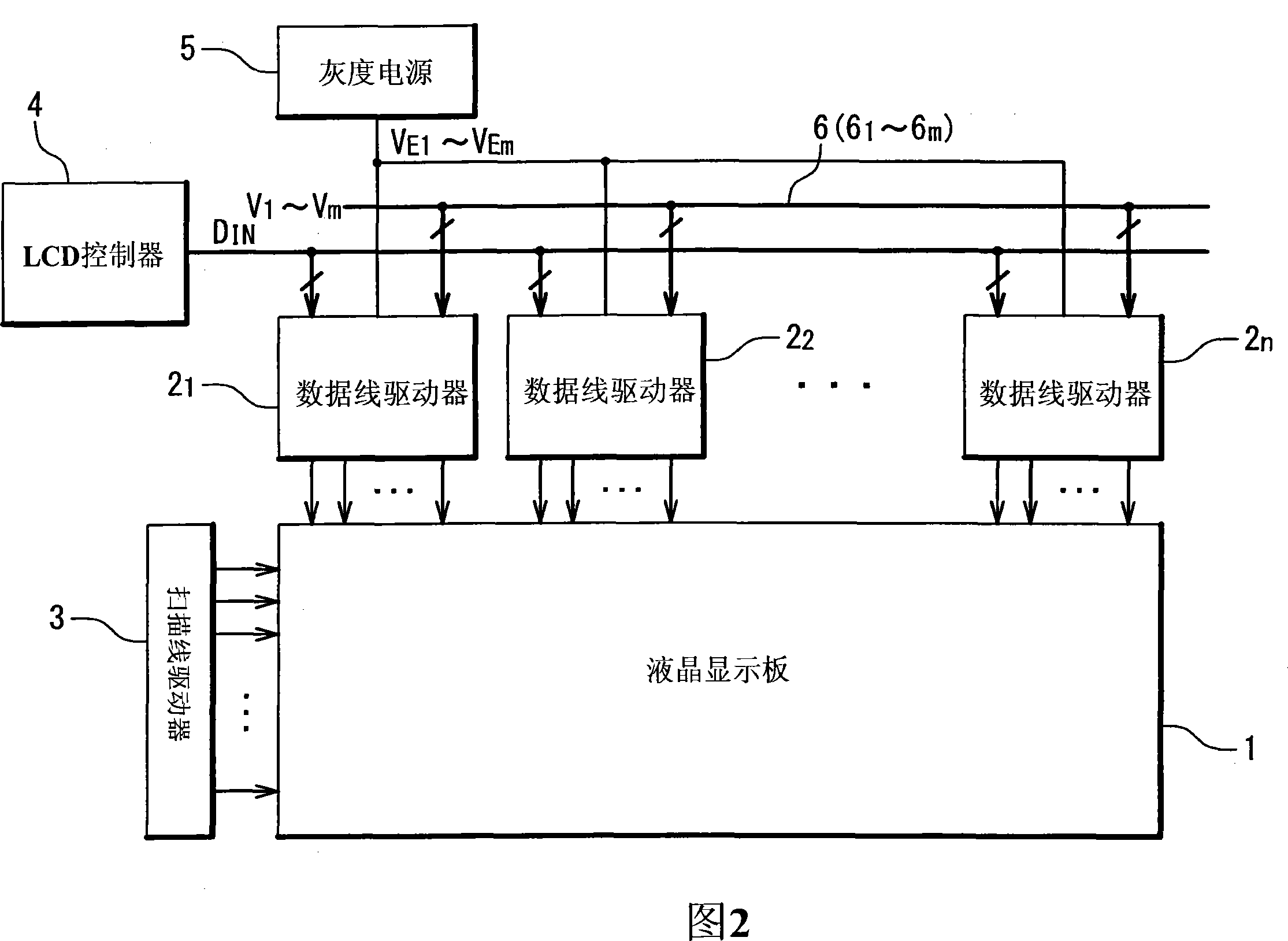
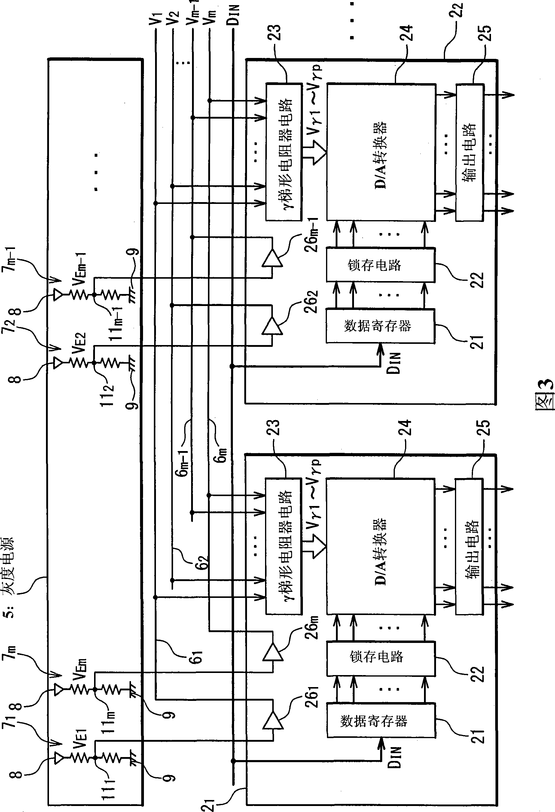
[0030] figure 2 is a block diagram showing the structure of the liquid crystal display device according to the first embodiment of the present invention. The liquid crystal display device includes: a liquid crystal display panel 1; a data line driver 2 1 to 2 n ; Scanning line driver 3; LCD controller 4; Data Line Driver 2 1 to 2 n The data lines (not shown) of the liquid crystal display panel 1 are driven. The scanning line driver 3 drives scanning lines (not shown) of the liquid crystal display panel 1 . LCD controller 4 to data line driver 2 1 to 2 n The pixel data D for displaying the gradation of each pixel on the liquid crystal display panel 1 is supplied IN . In addition, the LCD controller 4 gives the data line driver 2 1 to 2 n and scanning line driver 3 supply control signals (not shown), thereby controlling the data line driver 2 1 to 2 n and scan line driver 3 .

[0031] The grayscale power supply 5 is used to generate the grayscale power supply volt...

no. 2 example

[0049] Depending on the manufacture of each liquid crystal display device, the combination of reference voltages required by the manufacture of the liquid crystal display device may be different. More specifically, some manufacturing may require the supply of m reference voltages V 1 to V m to the data line driver, while another fabrication may require omitting the second maximum reference voltage V 2 and the second minimum reference voltage V m-1 supply.

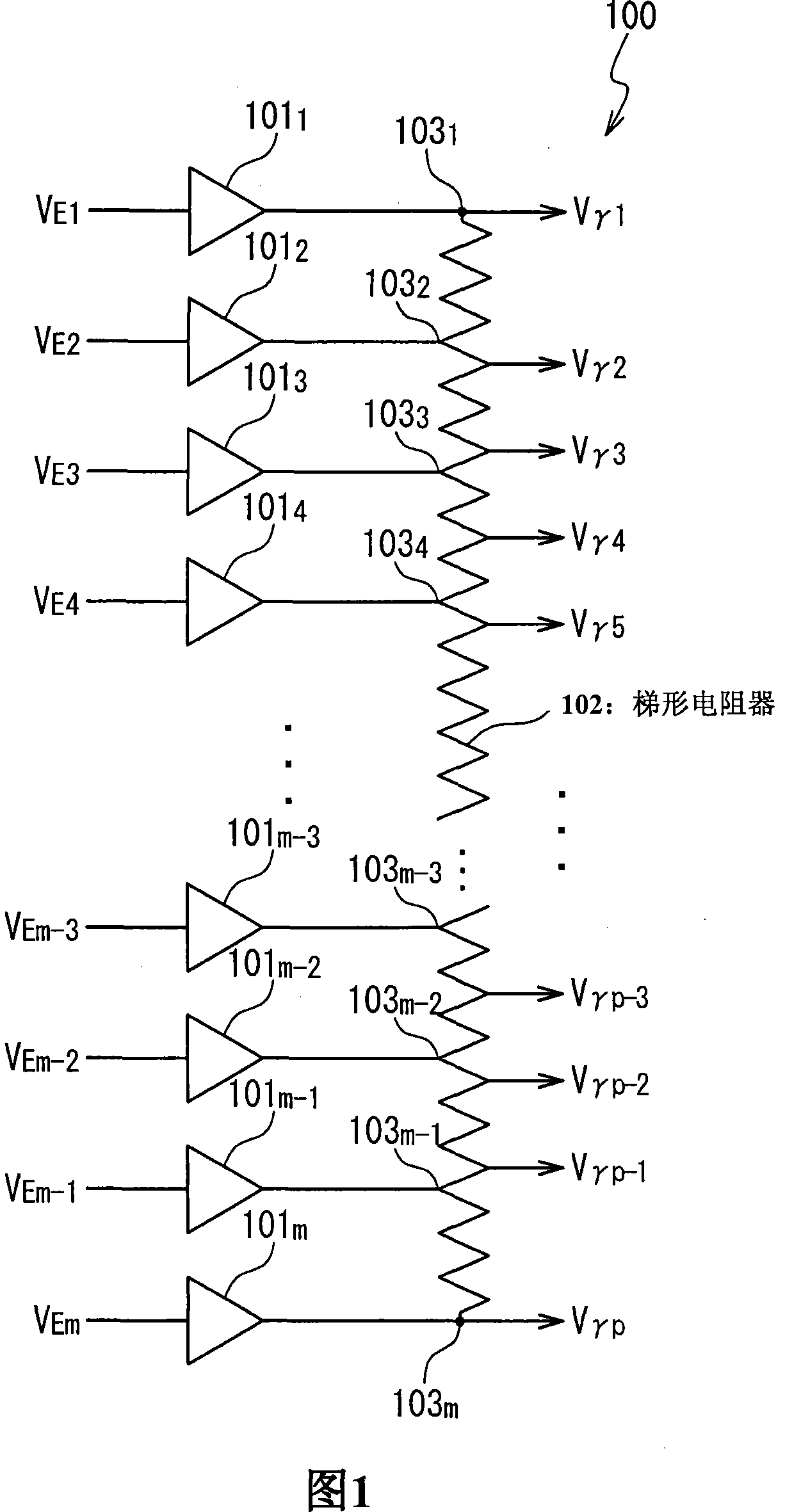
[0050] Figure 7 is shown in the absence of supply reference voltage V 2 and V m-1 Schematic diagram of the operation of the γ ladder resistor in the case of . Reference signs indicate the same Figure 4 The same components shown in. One of the problems that arises in meeting the above two manufacturing requirements at the same time is that, if Figure 7 shown in, if the reference voltage V is omitted 2 and V m-1 With the configuration of the gamma ladder resistor circuit 23 of the first embodiment, the required ...


PUM


Abstract

A display device includes: a display panel (1); at least one data-line driver (2); and a plurality of operational amplifiers (26 1 to 26 m-1). The plurality of operational amplifiers is integrated in any of the at least one data-line driver and generates a plurality of reference voltages, respectively. The data-line driver includes: a driving circuit, a maximum grayscale voltage wiring, and a resistance ladder. The driving circuit drives the display panel. The maximum grayscale voltage wiring receives a maximum reference voltage in the plurality of reference voltages from a first operational amplifier in the plurality of operational amplifiers and supplies the maximum reference voltage to the driving circuit as a maximum grayscale voltage. The resistance ladder receives the plurality of reference voltages except the maximum reference voltage from the plurality of operational amplifiers except the first operational amplifier, respectively, and generates a plurality of grayscale voltages lower than the maximum grayscale voltage. The driving circuit (24, 25) drives data lines of the display panel (1) by using the maximum grayscale voltage and the plurality of grayscale voltages. The maximum grayscale voltage wiring (27) is isolated from the resistance ladder (28).

Description

technical field [0001] The invention relates to a display device, a display panel driver and a display panel driving method. In particular, the present invention relates to a technique for generating grayscale voltages corresponding to grayscales. Background technique [0002] A display panel driver that drives a liquid crystal display panel and other display panels by a driving voltage is generally provided with a grayscale voltage generating circuit. The grayscale voltage generation circuit is a circuit for generating grayscale voltages corresponding to the respective grayscales used on the display panel. In a general display panel driver, a grayscale voltage generated in a grayscale voltage generation circuit is selected based on pixel data for displaying the grayscale of each pixel, and each pixel is driven by the selected grayscale voltage. [0003] Japanese Unexamined Patent Application JP-P-Heisei 6-161387A (corresponding to US5680148A) discloses a display device dr...

Claims


Application Information

Patent Timeline
Patent Type & Authority Patents(China)
IPC IPC(8): G09G3/20G09G3/36G02F1/133
CPCG09G2310/027G09G3/3688G09G3/36G02F1/133G09G3/20H02M3/06
Inventor 铃木健二
Owner RENESAS ELECTRONICS CORP
Why Eureka
Try Eureka