Switch of magnetic suspension train

A magnetic levitation and rotating ground technology, applied in transportation and packaging, railway car body parts, mechanical equipment for manipulating turnouts or line breakers, etc., can solve the problem of high partial load, complexity and cost of sliding bearings, shortening the life of sliding bearings And other issues

Active Publication Date: 2007-08-01
THYSSENKRUPP TRANSRAPID
View PDF1 Cites 4 Cited by
  • Summary
  • Abstract
  • Description
  • Claims
  • Application Information

AI Technical Summary

Problems solved by technology

This necessitates the provision of long and stable sliding bearings, so that the overall arrangement including beams and brackets is relatively complex and expensive
In addition, since the beams can be large in all three dimensions, higher stresses can occur in the beams during temperature changes and in particular inhomogeneous solar radiation, which distribute the load correspondingly unevenly to the slide bearings
This can lead to very high local loads of the slide bearing, in extreme cases a jamming of the slide bearing and also to a strong noise development of the slide bearing
As a result, the life of plain bearings is significantly shortened in some cases

Method used


Image

  • Switch of magnetic suspension train
  • Switch of magnetic suspension train
  • Switch of magnetic suspension train

Examples


Embodiment Construction

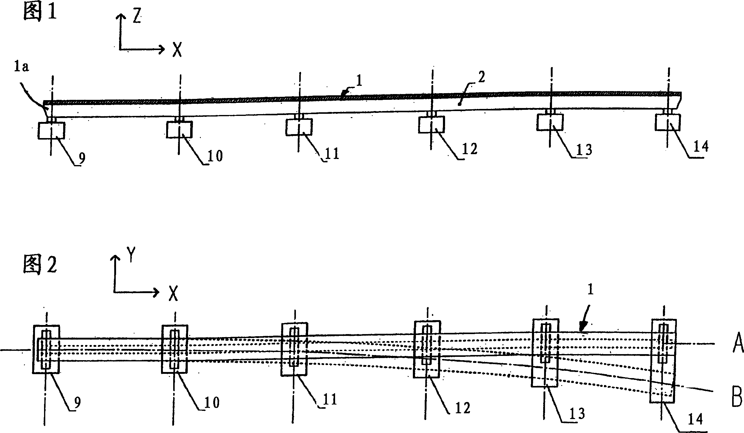
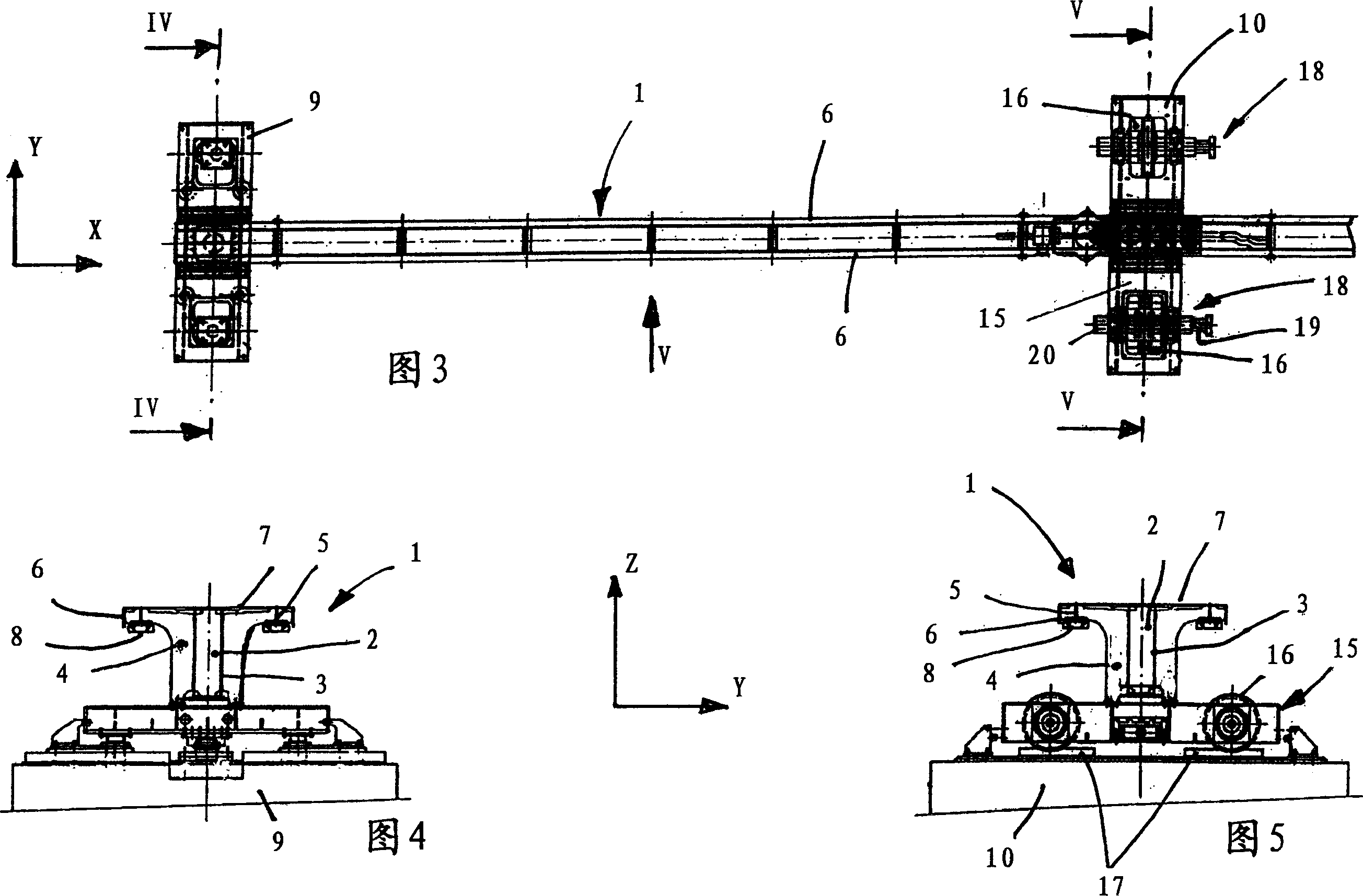
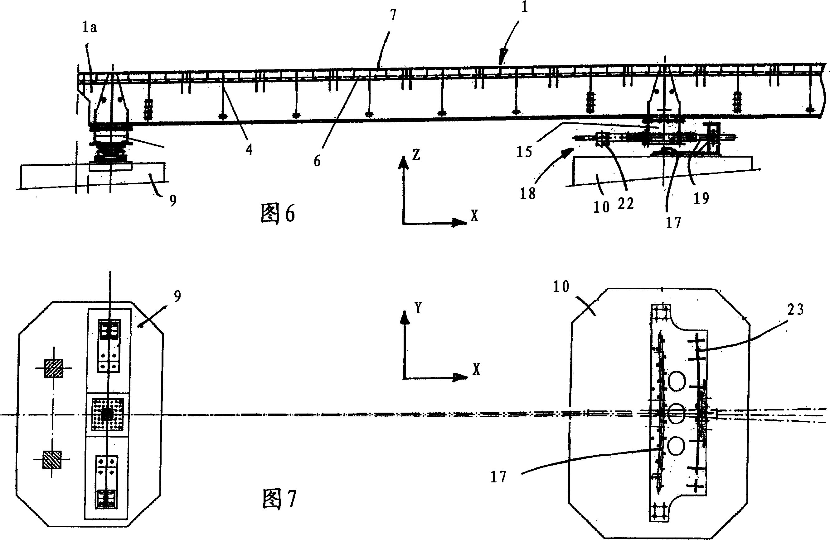
[0017] According to Figures 1 to 6, a common switch device in the form of a curve switch for a magnetic levitation vehicle comprises a bendable beam 1 made of steel and extending along the full length of the switch, which is for example about 50 m long or more long. The beam 1 comprises a support element 2 extending in the longitudinal direction (=x-direction), which preferably consists of a box-shaped profile, ie a hollow profile with a rectangular cross-section, wherein the height is greater than the width. As shown in particular in FIGS. 4 and 5 , the support element 2 comprises two webs or side parts 3 which are substantially vertical in the mounted state and arranged perpendicular to the ground. Between the side parts 3 there are transverse plates or partitions for reinforcement. On each side part 3 a bracket or support plate 4 protruding perpendicularly therefrom is fastened, at each end of which a slat 5 extending parallel to the respective side part 3 and arranged ver...


PUM


Abstract

Disclosed is a switch arrangement for magnetically levitated railways, comprising a support (1), which is bendable transversally to the direction of travel and is provided with track or component fittings, a rail (17) arranged transversally to the direction of travel, a rack (23) arranged transversally to the direction of travel and a supporting frame (15) for receiving said support (1). The supporting frame (15) is supported on the rail (17) by a running wheel (16) and comprises a drive mechanism (18) with a toothed wheel (20) that engages in the rack (23) as well as a motor for the propulsion thereof. According to the invention, the support (1), the supporting frame (15) and the drive mechanism (18) form, as an entity, a firmly connected assembly which is arranged in such a manner that it can be displaced in the direction of travel and relative to the rail (17) and the rack (23).

Description

technical field [0001] The invention relates to a switch arrangement of the type stated in the preamble of claim 1 . Background technique [0002] A switch device of a related type includes a so-called curve switch (for example "Magnet rail rapid transport - a new range of transport", Hestra publishing house, Darmstadt, 1989, 32 to 35 pages , DE 10 2004 015 495 A1). An important component of such a curve switch is a bendable beam made of steel, which is, for example, 50 m long or more and on which the roadway or the installation parts are supported. The beam is fixedly arranged at one end and is also mounted movably by means of a plurality of supports and rollers mounted thereon on rails, each rail being arranged transversely to its longitudinal direction, ie to travel. To adjust the point, the carriage can be moved back and forth along the track, whereby the beam turns and is selectively positioned on one of a plurality of roadways branched by the point. [0003] For the...

Claims


Application Information

Patent Timeline
Patent Type & Authority Applications(China)
IPC IPC(8): B61L5/02E01B25/34
CPCE01B25/34
Inventor 郑清华F·勒泽刘秀飞
Owner THYSSENKRUPP TRANSRAPID
Why Eureka
Try Eureka