Road information indicating system and method therefor
A road information and indication technology, applied in the field of electronic communication, can solve the problems of poor indication effect and easy occurrence of traffic hazards, and achieve the effect of reducing traffic accidents
- Summary
- Abstract
- Description
- Claims
- Application Information
AI Technical Summary
Problems solved by technology
Method used
Image

Examples
Embodiment Construction
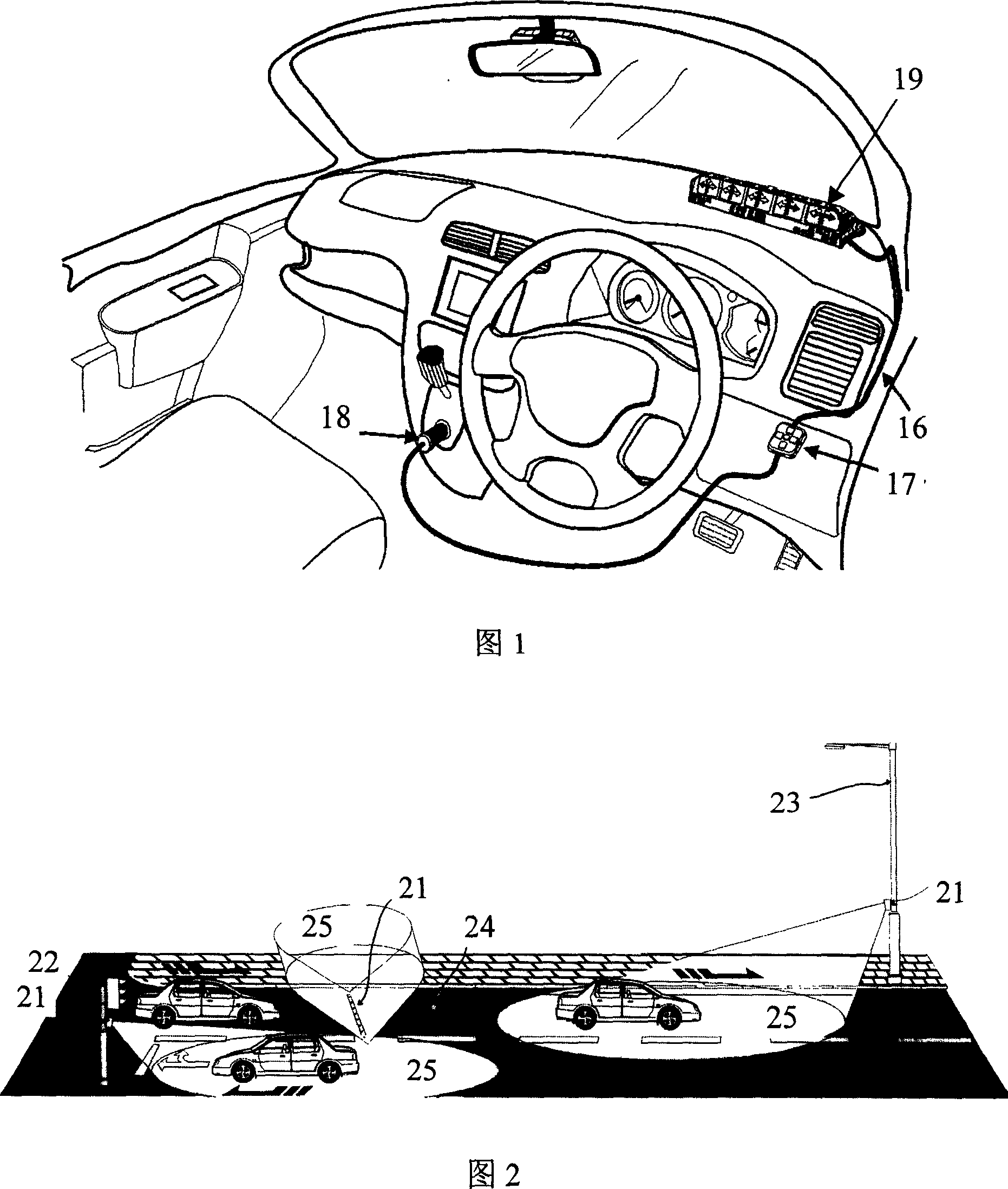
[0030] The present invention relates to a road traffic information indicating system, as shown in FIG. 2 . The system includes a coded data transmitting device 21 installed beside the road, which can emit infrared beams or radio waves. This launcher 21 can be installed on traffic signal lamp 22 or street lamp 23 or overhead beam or roadside building surface or road surface 24, and it must be connected to power supply, commercial power or other energy sources such as solar energy or battery power supply etc. also can.
[0031] The infrared or radio wave signal emitted by the transmitting device 21 is irradiated or transmitted to the receiving device 11 (as shown in FIG. 1 ) on the moving vehicle with the shortest distance. One or more transmitters 21 can be installed on each road, and the installed quantity can depend on how many branch exits of the road and the required degree of reliability. Generally speaking, the more branch intersections, the more launching devices 21 are...
PUM
 Abstract
Description
Claims
Application Information
 - Generate Ideas
- Intellectual Property
- Life Sciences
- Materials
- Tech Scout
- Unparalleled Data Quality
- Higher Quality Content
- 60% Fewer Hallucinations
Browse by: Latest US Patents, China's latest patents, Technical Efficacy Thesaurus, Application Domain, Technology Topic, Popular Technical Reports.
© 2025 PatSnap. All rights reserved.Legal|Privacy policy|Modern Slavery Act Transparency Statement|Sitemap|About US| Contact US: help@patsnap.com