Plumbing fixture

A technology of a sanitary device and a control device, applied in the field of sanitary devices, can solve the problems of user burns, user misoperation and the like

Inactive Publication Date: 2007-08-01
HANSA METALLWERKE AG
View PDF7 Cites 5 Cited by
  • Summary
  • Abstract
  • Description
  • Claims
  • Application Information

AI Technical Summary

Problems solved by technology

That is, the thermostat handle must be arranged so that the proximity switch cannot be inadvertently operated during its operation, as

Method used


Image

  • Plumbing fixture
  • Plumbing fixture

Examples


Embodiment Construction

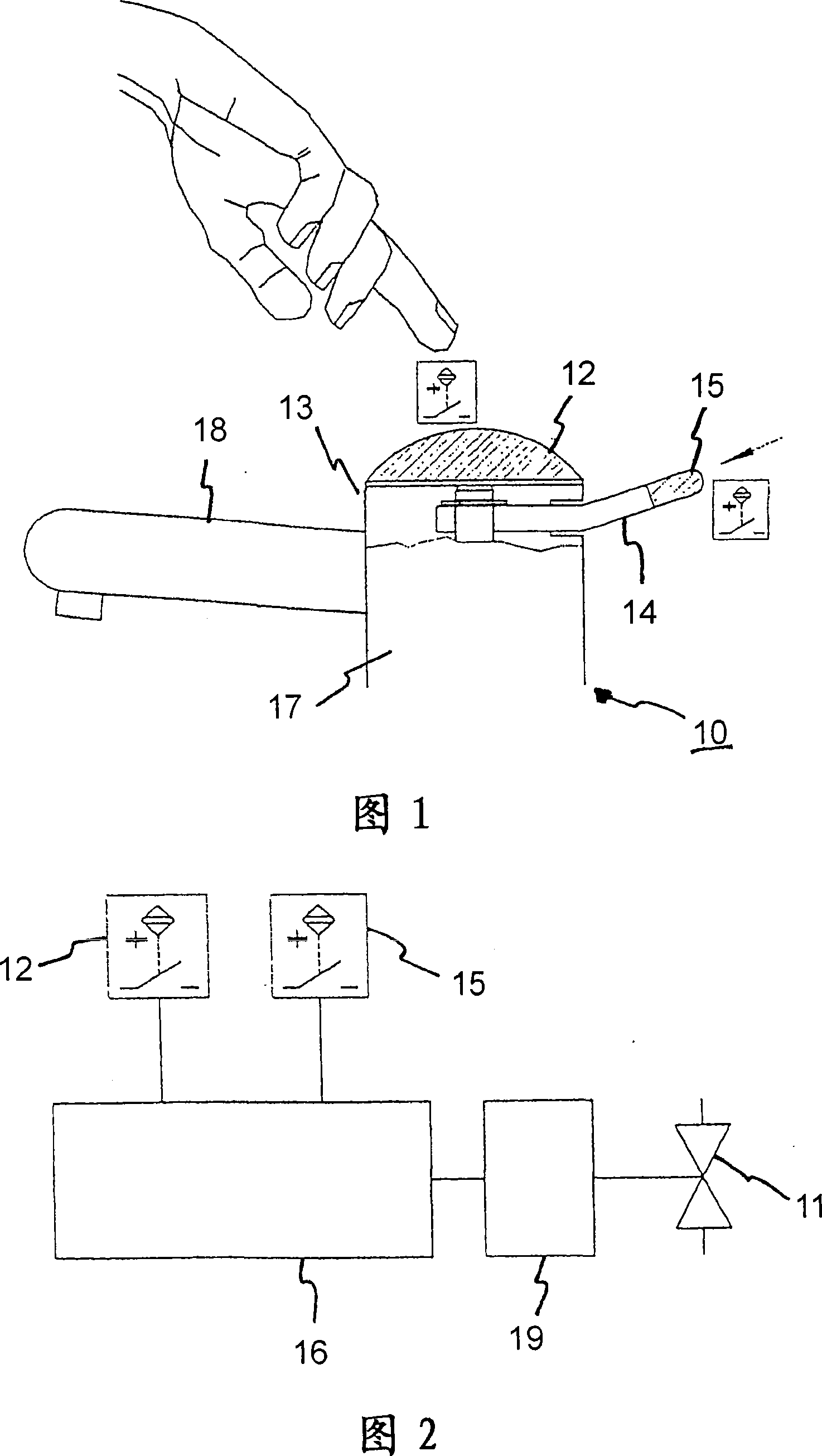
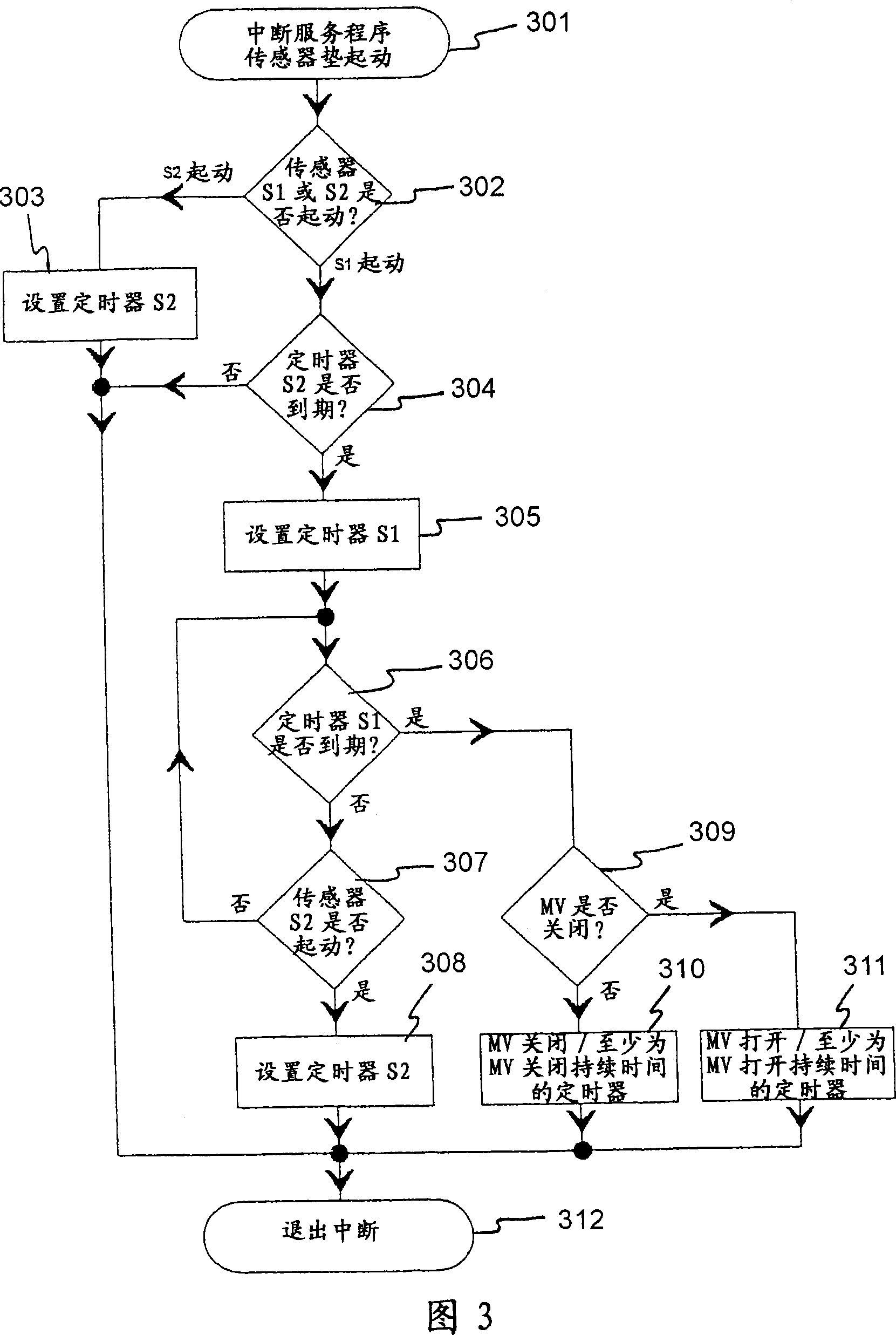
[0021] FIG. 1 shows a schematic illustration of a sanitary installation 10 . The sanitary device 10 has a cylindrical base body 17, on the front side of which a forward-pointing outflow tube 18 is arranged. Installed inside the plumbing fixture is an electrically operated valve (not shown) through which the flow of water can be turned on and off.

[0022] A proximity switch 12 is mounted in the full-circle head section 13 of the base body 17 , via which the valve is actuated. A mixer (not shown) is also arranged inside the sanitary device, which is connected to domestic hot water and cold water connections and mixes incoming hot and cold water in an adjustable ratio. A temperature control handle 14 is provided for actuating the mixer, which is arranged on the rear side of the sanitary device 10 opposite the outflow tube 18 . The mixing ratio in the mixer is adjusted by swinging the thermostat handle 14 sideways.

[0023] Actuation of the proximity switch 12 generates a puls...


PUM


Abstract

Disclosed is a plumbing fixture (10) comprising an electrically actuated valve (11) by means of which a water flow that penetrates the plumbing fixture (10) can be turned on and off. A first switch (12) that is embodied as a proximity switch is used for opening the valve (11) and thus starting the water flow. The inventive plumbing fixture additionally comprises a mechanically actuated operator's element (14) which is used for regulating another function of the plumbing fixture (10), such as the water temperature or the water quantity. A second switch (15) that is used for electrically blocking the first switch (12) is assigned to the mechanically actuated operator's element (14). For this purpose, the second switch (15) is disposed so as to respond when the additional operator's element (14) is manipulated.

Description

technical field [0001] The invention relates to a sanitary fixture (sanitary fixture) with an electrically operated valve for controlling the flow of water through the sanitary fixture, the sanitary fixture having a first switch designed as a proximity switch for opening the valve, and A mechanically actuatable operating element for adjusting other functions of the sanitary installation. Background technique [0002] Sanitary fixtures such as taps etc. are known to be opened by proximity switches and automatically closed after a certain time interval. In some cases these plumbing fixtures also have a thermostat handle for manually adjusting the water temperature. Some limitations arise here in the arrangement of the thermostat handle. That is, the thermostat handle must be arranged such that the proximity switch cannot be inadvertently operated during its operation, as this would cause the user to mishandle and in extreme cases present a risk of scalding to the user due to...

Claims


Application Information

Patent Timeline
IPC IPC(8): E03C1/05
CPCE03C1/057E03C1/0412
Inventor H·孔克尔
Owner HANSA METALLWERKE AG
Why Eureka
Try Eureka