Method and device for motion estimation and compensation for panorama image

A panoramic image and motion estimation technology, applied in the field of motion estimation and compensation, can solve unavailable problems, increase efficiency and accuracy, and improve image quality

Active Publication Date: 2007-08-01
UNIV IND COOP GRP OF KYUNG HEE UNIV +1
View PDF0 Cites 45 Cited by
  • Summary
  • Abstract
  • Description
  • Claims
  • Application Information

AI Technical Summary

Problems solved by technology

[0007] However, sometimes, depending on the position of the current macroblock X in the current frame, some previous macroblocks adjacent to the current macroblock X are not available when estimating the motion vector of the current macroblock X

Method used


Image

  • Method and device for motion estimation and compensation for panorama image
  • Method and device for motion estimation and compensation for panorama image
  • Method and device for motion estimation and compensation for panorama image

Examples


Embodiment Construction

[0042] best practices

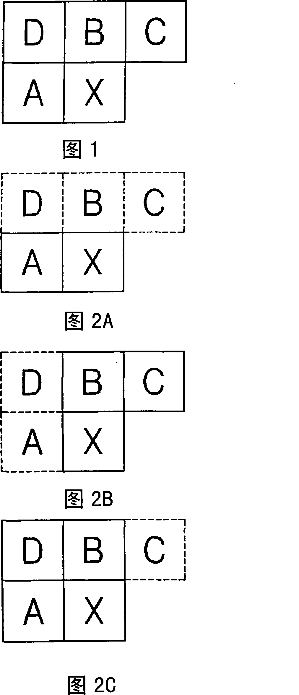
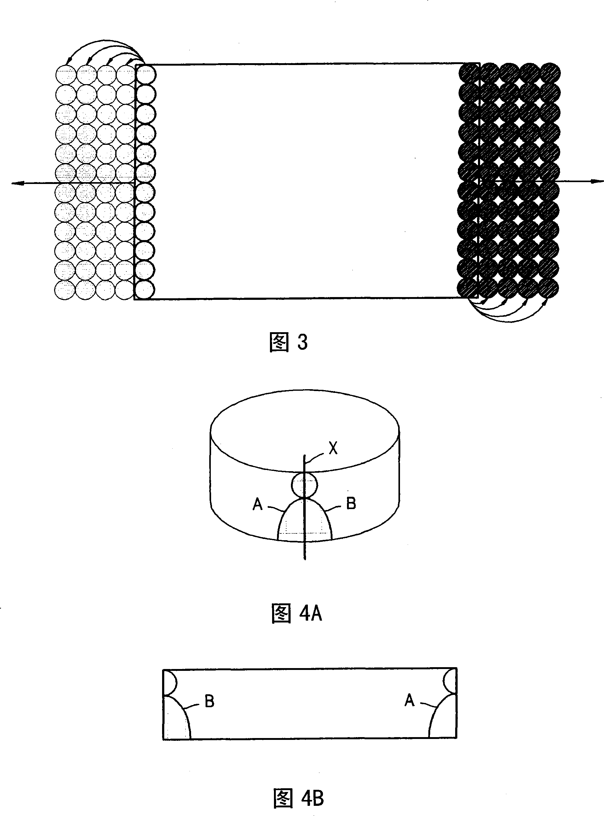
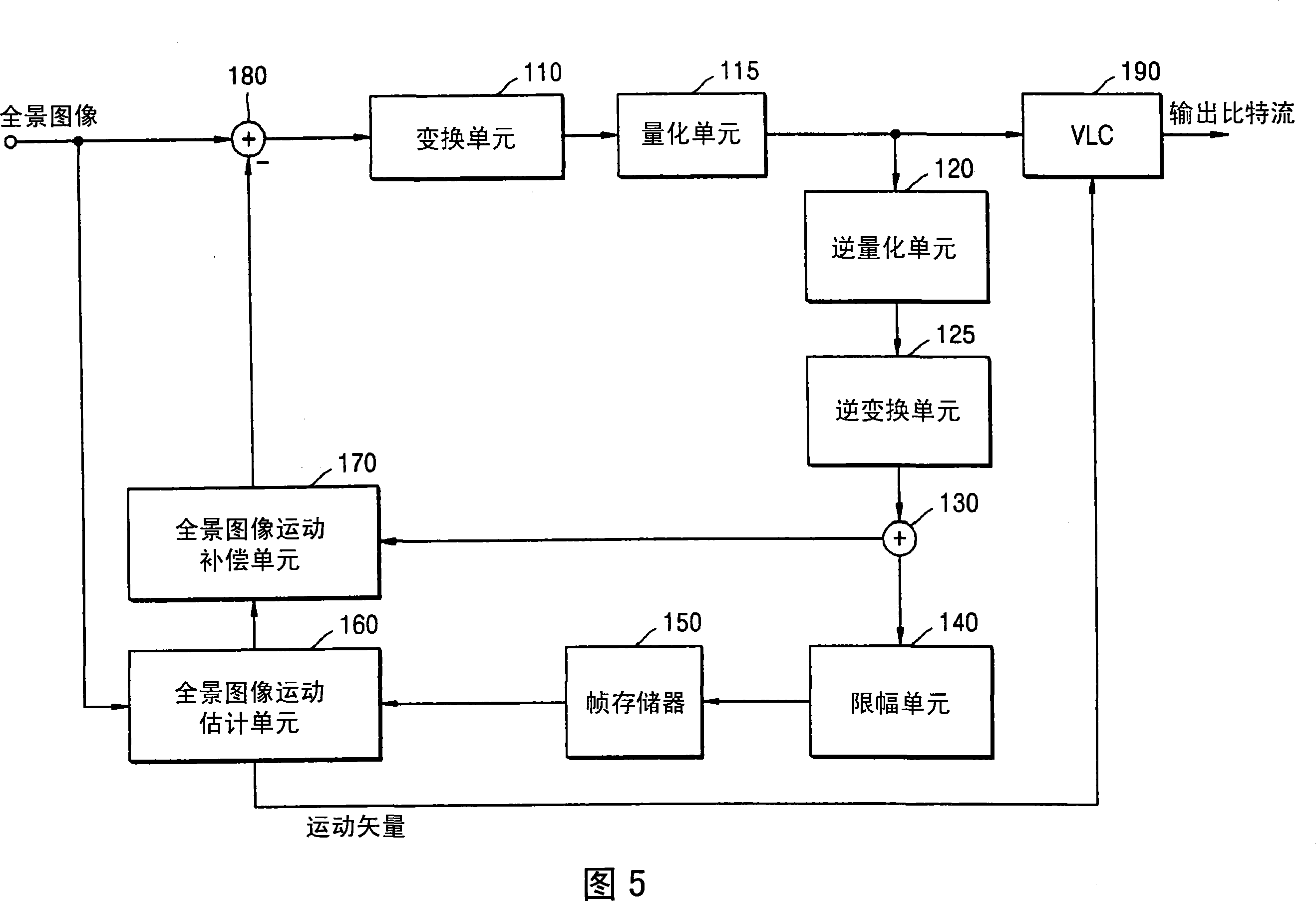
[0043] According to an aspect of the present invention, a method for estimating motion of a panoramic image containing 360° omnidirectional view information is proposed. The method includes: using a right boundary area of ​​a basic reference frame to fill a filling area connected to a left side of a basic reference frame, the basic reference frame being used for motion estimation of a panoramic image. The method further includes: filling a padding area connected to a right side of the basic reference frame with a left border area of ​​the basic reference frame; and forming a reference frame by extending the filled basic reference frame. The method continues to estimate the motion vector of the current data unit of the panoramic image using a plurality of previous data units adjacent to the current data unit. When the sub-pixel belongs to the reference frame, the value of all the pixels of the reference data unit represented by the motion vector estimat...


PUM


Abstract

Provided are a method and device for motion estimation and compensation to be performed on a panorama image. The motion estimation and compensation are performed on a panorama image with a 360 DEG omni-directional view based on that the spatial relation between left and right borders of the panorama image is very high. Accordingly, it is possible to improve image quality through effective and precise estimation and compensation for the motion of a panorama image. In particular, it is possible to improve the image quality at the right and left edges of the panorama image.

Description

technical field [0001] The present invention relates to motion estimation and compensation of panoramic images. More specifically, the present invention relates to a method and apparatus for estimating motion of a panoramic image containing 360° omnidirectional image information, and a method and apparatus for compensating for motion of the panoramic image. Background technique [0002] An omnidirectional video camera system is an omnidirectional camera system capable of obtaining a 360° omnidirectional view from a single viewing angle. The omnidirectional camera system includes a camera mounted with a mirror of a specific shape such as a hyperboloid mirror, or a specific lens such as a fisheye lens, or may include multiple cameras to obtain a 360° viewing angle. [0003] A three-dimensional (3D) realistic broadcasting system can be applied to omni-directional video encoding. As an example of a 3D realistic broadcast service, the viewer terminal receives all image informat...

Claims


Application Information

Patent Timeline
Patent Type & Authority Applications(China)
IPC IPC(8): H04N7/24H04N19/105H04N19/134H04N19/136H04N19/139H04N19/176H04N19/196H04N19/20H04N19/423H04N19/50H04N19/51H04N19/513H04N19/563H04N19/625H04N19/91
CPCH04N19/0063H04N19/0066H04N19/00587H04N19/00642H04N19/00696H04N19/00666H04N19/51H04N19/52H04N19/523H04N19/55H04N19/56H04N19/563H04N5/265H04N19/50
Inventor 朴光勋孙星镐
Owner UNIV IND COOP GRP OF KYUNG HEE UNIV
Why Eureka
Try Eureka