Machining liquid processing apparatus for electrospark wire processing apparatus

A processing device and electric spark wire technology, which is applied in the field of processing fluid processing devices, can solve problems such as temperature rise, reduction in processing accuracy, wire electrode disconnection, etc., so as to reduce the temperature change of the processing fluid, improve the processing accuracy, and suppress thermal deformation. Effect

Inactive Publication Date: 2007-08-08
FANUC LTD
View PDF3 Cites 9 Cited by
  • Summary
  • Abstract
  • Description
  • Claims
  • Application Information

AI Technical Summary

Problems solved by technology

[0015] Among the above-mentioned conventional processing fluid processing devices, the processing fluid processing device shown in FIG. 2 does not control the temperature of the processing fluid in the processing tank 2, and the cooled processing liquid is directly supplied to the processing tank 2. 5. Since the machining fluid that has not been cooled is supplied, the temperature of the machining fluid in the machining tank 2 is unstable and uneven, so that the shrinkage of the table or the workpiece in the machining tank 2 due to thermal deformation becomes large and the machining accuracy is reduced. reduction, or the cause of wire electrode disconnection
[0016] In addition, in the processing fluid processing apparatus of the conventional example shown in FIG. The machining fluid is supplied between the wire electrode and the workpiece, and the machining fluid heated by the heat loss of the circulation pump P3 or the jet pump P2 is supplied to the machining tank 2, so the temperature of the machining fluid in the machining tank 2 rises, and The problem of not being able to obtain a uniform temperature
[0017] In addition, in the processing fluid treatment device of the conventional example shown in FIG. 4, there is a problem that two processing fluid cooling devices are required, and the overall cost of the device is high.

Method used


Image

  • Machining liquid processing apparatus for electrospark wire processing apparatus
  • Machining liquid processing apparatus for electrospark wire processing apparatus
  • Machining liquid processing apparatus for electrospark wire processing apparatus

Examples


Embodiment Construction

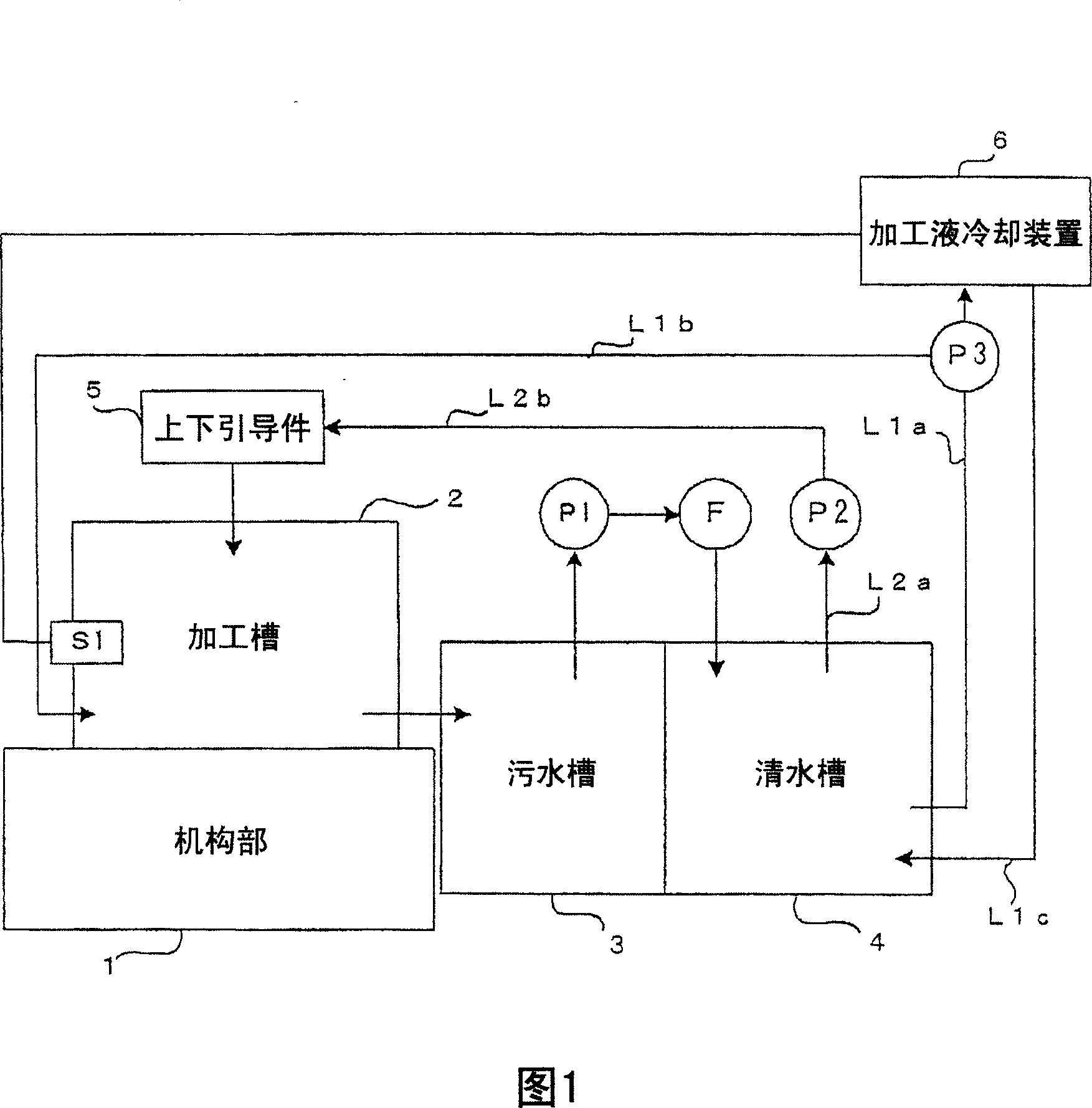
[0025] FIG. 1 is a schematic block diagram of a machining fluid processing device according to an embodiment of the present invention. On the other hand, the same elements as those of the conventional working fluid processing apparatus are denoted by the same reference numerals.

[0026] Similar to the conventional machining liquid processing apparatus, a machining tank 2 is provided in the mechanism part 1 of the wire electric discharge machining apparatus, and an electric discharge machining part is provided in the machining tank 2 . That is, the workpiece (processed object) is installed on the mechanism part 1 and mounted on the table, a voltage is applied between the workpiece and a wire electrode not shown to generate a discharge, and the wire electrode is relatively moved with respect to the workpiece, thereby EDM the workpiece.

[0027] In addition, the machining fluid is supplied to and stored in the machining tank 2 . The machining fluid in the machining tank 2 is m...


PUM


Abstract

A temperature sensor for detecting a machining liquid temperature in a machining tank is provided. A machining liquid cooling device controls machining liquid in a clean water tank based on the temperature detected by the temperature sensor and returns the machining liquid to the clean water tank. The machining liquid in the clean water tank is supplied to the machining tank and wire guides through pumps. Because the machining liquid temperature in the clean water tank is controlled based on the machining liquid temperature in the machining tank, it is possible to maintain the machining liquid in the machining tank substantially at a target temperature, even though the machining liquid is supplied after being heated by the pumps.

Description

technical field [0001] The present invention relates to an improvement of a machining fluid treatment device for controlling the temperature of machining fluid included in a wire electric discharge machining device. Background technique [0002] A wire electric discharge machining device is a machine that applies a voltage between a wire electrode and a workpiece (workpiece) to generate electric discharge to machine the workpiece. In order to remove machining chips generated by insulation, cooling, and discharge between the wire electrode and the workpiece, a machining liquid is interposed between the wire electrode and the workpiece. The machining fluid is heated by the electric discharge between the wire electrode and the workpiece, and its temperature rises. Furthermore, the temperature rises due to heat loss from a pump that supplies the machining fluid to, for example, a machining tank in which the workpiece is disposed. [0003] As the temperature of the machining fl...

Claims


Application Information

Patent Timeline
Patent Type & Authority Applications(China)
IPC IPC(8): B23H1/10B23H7/36
CPCB23H1/10B23H7/36
Inventor 喜多佑树西川亮
Owner FANUC LTD
Why Eureka
Try Eureka